Just measuring the magnitude of the gain without measuring the phase doesn't give the complete information neccesary to optimise the closed loop. If both the magnitude and phase behavior is known the closed loop can be optimised and better stabilisation methods than dominant pole can be used. Many solid state designers chose not to make a complete measurement of magnitude and pase of the open loop and just slam enough capacitance as compensation so that the closed loop is stable. For tube designs this is a bit different as the available loop gain is normally less and it can therefore be worthwhile to use all of the open loop gain as high up in frequency as possible, therefore the dominant pole method is never used and more or less advanced phase compensation methods are used instead. One example is my own OTL tube amplifier which has an open loop 3dB point at ~500kHz and where I have measured gain and phase response up to 20MHz thereby making it possible to keep the amount of feedback constant up to ~250kHz by using phase compensation networks. Using brute force and domninant pole this would have needed a pole at less than 10kHz to guarantee stability.
Similar compensation methods are indeed used in some high quality solid state amplifiers so I assume that those designers must have measured the complete magnitude and phase response in open loop in order to design those compensation networks.
Regards Hans
Similar compensation methods are indeed used in some high quality solid state amplifiers so I assume that those designers must have measured the complete magnitude and phase response in open loop in order to design those compensation networks.
Regards Hans
Hi John
I did the OLG measurement exactly according your instructions in a small amplifier module intended to use in my preamplifier project as a discrette device operational amplifier. I haven't the time to export the measurements in *.jpeg format and the schema of module. Moreover the topology used it is a mix of well known topologies - no one discovery - from power amplifiers and operational amplifiers, implemented in equivalence between them. The only that may mentioned it is its CFP output. Nothing else.
Well, your method (and may quoted also the suggestion of Glen) was absolutelly effective and the proccess also was very stable! No one problem, clear and stable graphs on my DSO screen! For the record i devided the Rf of 10K in two 5K and i used a cap of 4700ìF for the AC coupling in gnd node.
I can give you the results by numbers to the present:
1) Input sinus 100Hz/20mVpp--> Output 3,2Vpp--> Av=44dB
2) Input sinus 1KHz/20mVpp--> Output 3,2Vpp--> Av=44dB
3) Input sinus 10KHz/20mVpp--> Output 2,92Vpp--> Av=43,3dB
4) Input sinus 20KHz/20mVpp--> Output 2,36Vpp--> Av=41,4dB
I think the results are very satisfactory because i put these discrete device modules in a Closed Loop Gain of 1.
Also the phase shift begins from 2KHz at 10deg, in 20KHz touches the 25deg which may be a satisfactory little deviation.
Thanks a lot for your advices.
Fotios
Hi John and Fotios,
I'm have some difficulties trying to understand the difference I have between OLG results when
1/ simulating OLG using Tian probe and using and
2/ simulating the practical options to measure OLG ==> split feedback resistor and big capacitor to ground.
Picture 1: bode plot with OLG using Tian probe
Picture 2: implemented split feedback resistor and cap to ground and input signal of 1kHz 5mv peak
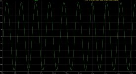
Picture 3: Output signal using the split feedback resistor
Result in OLG with split feedback resistor = gain (28.65/0.005) = x5730 = 75dB. Using tian probe gives 46dB.
?? now that I'm writing this is see a difference of 29dB which is equal to the CLG?!
Can it be that the Tian probe does not gives me the OLG?
BTW: calculating the gain using the output signal and error signal in the input stage gives exactly the same as the split feedback resistor measurement.
Can it be that the tian probe
I'm have some difficulties trying to understand the difference I have between OLG results when
1/ simulating OLG using Tian probe and using and
2/ simulating the practical options to measure OLG ==> split feedback resistor and big capacitor to ground.
Picture 1: bode plot with OLG using Tian probe
Picture 2: implemented split feedback resistor and cap to ground and input signal of 1kHz 5mv peak
Picture 3: Output signal using the split feedback resistor
Result in OLG with split feedback resistor = gain (28.65/0.005) = x5730 = 75dB. Using tian probe gives 46dB.
?? now that I'm writing this is see a difference of 29dB which is equal to the CLG?!
Can it be that the Tian probe does not gives me the OLG?
BTW: calculating the gain using the output signal and error signal in the input stage gives exactly the same as the split feedback resistor measurement.
Can it be that the tian probe
Attachments
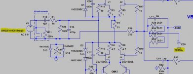
Open Loop Gain (as measured by the split feedback resistor) is not the same with the Loop Gain (as measured by the Tian probe method).
LG=1+OLG*T
where LG is the loop Gain, OLG is the Open Loop Gain and T is the feedback factor. These quantities are frequency dependent (or complex, if you prefer), so it is not straightforward to relate them.
In your case, at low frequencies, T could be approximated as R36/(R29+R44+R48+R53) or about -29dB. It follows that your Loop Gain~75dB-29dB=46dB which is exactly what the Tian method gives for the Loop Gain. Both your measured and calculated results seem correct, however you need the frequency dependency of the Loop Gain to estimate the stability which, as I already mentioned, is far from trivial. For large Open Loop Gains, extracting the Loop Gain this way is doomed to fail.
Thanks Waly,
I understand that these parameters are frequency dependent. Offcourse I have to perform this measurement on a range of frequencies going from about 10Hz to +-20Khz. In this range I should be able to calculate the open loop bandwidth which matters to me for the moment.
The only tools I have are a frequency generator and a 2 channel 20Mhz scope.
The split feedback resistor measurement I should be able to do. Fotios had good experience with it.
If other options are there with the above tools to measure OLG or LG, I'm more than interested.
Kind regards
Well, no... You would have to perform these measurements up to what is called the Unity Loop Gain Frequency (ULGF), which is the frequency at which the Loop Gain becomes 1 (0dB). Then 180 - the phase at that frequency will give the "phase margin". And the Loop Gain at phase=180 will give the "gain margin". ULGF is usually in the MHz range.
Theoretically, knowing the Open Loop Gain and the Closed Loop Gain you can calculate the Loop Gain as LG=OLG/CLG at each frequency point. This is almost impossible in practice, since even something like 16bit of precision in magnitude and phase will still lead to errors that would completely obscure the desired results around the ULGF. An oscilloscope trace is at best around 5%, also measuring the phase is virtually impossible.
To make accurate measurements you need something like this 404 Not Found or a dual channel vector network analyzer, running at a minimum of 10MHz (the Agilent 89410A is a good example). Another good one is the Agilent 4195A. These are all old boat anchors, and can be purchased from second hand equipment dealers for less than a new Omicron-lab device. If memory serves, Analog Devices sells a device that would allow you such measurements, and I recall it is fairly priced for educational purposes.
The principle of reliable loop gain measurements is described here: http://www.ti.com/lit/an/snva364a/snva364a.pdf
But other than for educational purposes (or natural curiosity) accurate loop gain measurements for audio DIY purposes is not really required; the Spice stock models and the usual engineering design margins are good enough to trust the simulation results. Of course, if you want to design a power amplifier with 8-10MHz ULGF (perfectly possible in principle) or if you want to use a 5th order compensation, then indeed you would need accurate measurements to validate the simulation results. But usually this is beyond the scope of DIY activities and ultimately not at all required for good audio performance. I've seen a few heroic audio designs, pushing the loop gain and the compensation order to the limits of decent stability, usually at the price of a huge complexity, one is PGP In my book such designs are good only for the bragging rights of breaking an imaginary barrier of 1ppm distortion @20KHz. Otherwise, not even bats may hear any improvement over any decent Miller compensated amplifier.
Last edited:
If memory serves, Analog Devices sells a device that would allow you such measurements, and I recall it is fairly priced for educational purposes.
Affordable and portable USB oscilloscope, logic analyzer, function generator, and digital I/O
But other than for educational purposes (or natural curiosity) accurate loop gain measurements for audio DIY purposes is not really required; the Spice stock models and the usual engineering design margins are good enough to trust the simulation results.
Well, I wish this was the case with mosfets to. I have soundwise very good results in a previous diy amp using 2sk216 and 2sj79. I have luckily some in stock of these and I have these currently in the VAS of a new prototype. I haven't found any good spice models for these and spend quite some houres in changing these models to have datasheet like curves. But did not achieve good enough results certainly concerning all the capacitance parameters which are important in a VAS section and influence the Bode plot quite a lot.
Would even pay someone if they could help me further with these models.
Back again")
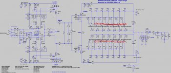
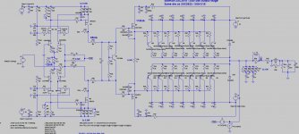
I've tried to make some Loop gain measurements from the circuit below.
What have I done:
1. freq generator at input with LP + HP input filter connected
2. Set the output voltage at different rms voltages: 1V and 2V
3. Measured the voltages over de + and - input of the diff stage. This has
been done with a fluke 8808A in relative measurement modus.
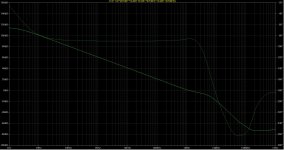
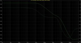
Results are as per graph below and seems not right
1. Loopgain at 2Vrms out is higher than 1Vrms out? Loopgain is not output
voltage dependant if I'm not mistaking?
2. Graph is not what I expected. Don't know how accurate spice is for gain
measurements, but I have about 20dB difference between spice and
measurements. Remarkt the dB's in the graph are the measured ones,
minus the 29dB feedback.
Any ideas or advise what I'm doing wrong?
Thanks
I've tried to make some Loop gain measurements from the circuit below.
What have I done:
1. freq generator at input with LP + HP input filter connected
2. Set the output voltage at different rms voltages: 1V and 2V
3. Measured the voltages over de + and - input of the diff stage. This has
been done with a fluke 8808A in relative measurement modus.
Results are as per graph below and seems not right
1. Loopgain at 2Vrms out is higher than 1Vrms out? Loopgain is not output
voltage dependant if I'm not mistaking?
2. Graph is not what I expected. Don't know how accurate spice is for gain
measurements, but I have about 20dB difference between spice and
measurements. Remarkt the dB's in the graph are the measured ones,
minus the 29dB feedback.
Any ideas or advise what I'm doing wrong?
Thanks
Attachments
Last edited:
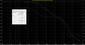
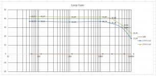
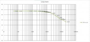
I've done a new loop gain measurement.
Values are consistent with previous measurement.
Output rms voltage is 5V.
Measured up to a frequency of 200KHz.
Notice that gain is dropping with more than 20dB/decade.
Could it be that the input impedance of the fluke 8808A can have an impact on OLG? Input impedance is 1M shunted with 100pF, according spice, this should have as good as no impact.
Why is it that measured LG is that low compared with spice? 40dB VS 60dB at 1Khz?
Shematic: https://www.diyaudio.com/forums/sol...in-measurement-fotios-help-3.html#post5542972
Attachments
To make accurate measurements you need something like this 404 Not Found or a dual channel vector network analyzer, running at a minimum of 10MHz (the Agilent 89410A is a good example). Another good one is the Agilent 4195A. These are all old boat anchors,
Hi, Waly, have you used an 89440A for loop gain measurements? The Agilent sweeper demo seems to apply a chirp waveform repeatedly and then sort it out by FFT over many chirps. It seems to work, but it probably takes a hit on dynamic range. I have spent the last weekend and part of this week to write a control program to automate this, including feeding gnuplot with the measurement results to produce the Bode diagram.
There were a lot of things that work differently than the way I assumed, including units, setting the input range and many other things that I simply had to try in different ways. And don't think that you can ctl-C & ctl-V command strings from the manual, the single quotes in the manual are something completely different from what the SCPI parser expects. Sometimes also double quotes. But it seems to converge now.Probably I'll have to adjust transmission power and input sensitivity on a decade base to get non-noisy results, esp. for phase.
cheers, Gerhard
Your input measurement may be noise-limited. Trying to measure loop gain directly is tricky business.Why is it that measured LG is that low compared with spice? 40dB VS 60dB at 1Khz?
I suggest you configure the amp for very high AC gain (unity at DC) - maybe something like 100 kOhm / 1 ohm + 10000µF-ish electrolytic (the cap probably best being paralleled by another 1000µ plus 100µ). Then calculate back to remove any remaining deviation - solve the OLG --> CLG formula for OLG. (To eliminate the effect of the capacitor, replace R_g by R_g + Z_cap for a frequency-variable noise gain term.)
A variable 0/20/40/60 dB attenuator on the input side is likely to prove handy. Also make sure you use an FFT or other way of filtering out just the desired frequency so you don't get in trouble with noise again.
One point to bear in mind is that if you use large capacitors to decouple the NFB to measure OLG, the frequency response may be limited if the capacitor is not large enough - it has to be comparable to the grounding resistor impedance divided by the (expected) OLG -in other words very large. If this is what you are using, try simulating the OLG using AC simulation and see whether it reaches a plateau somewhere around 100Hz-1kHz: if not, it probably is not large enough decoupling.
For real OLG measurements you will need significant attenuation of the input - I use typically 1 or 10 ohms fed through 10k (10000:1 or 1000:1) reduction.
If the purpose of your LG measurements is to determine the phase margin you will need to measure the performance up to the unity loop gain frequency as Wally pointed out, which is much more difficult without the right kit. Analog Devices show how to use a transformer to inject a signal into the feedback path. You may be able to get an idea of the phase from an oscilloscope if you can compare the injected signal phase with the output.
My main concern with a Class AB output stage is that simulation using AC only works for the DC conditions calculated, not over the full range of operating currents/voltages that the amplifier could see in the AB stages, so even simulation with AC signals might not reveal instabilities.
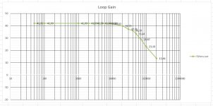
Hi,
My goal of these measurements is finding out where approx the -3dB point is, also known as open loop bandwitdh. For determening phase margin, this is out of my league due to limited tools.
In the mean time, I have performed loop gain measurements according you suggested method: https://www.diyaudio.com/forums/sol...gain-measurement-fotios-help.html#post1476652
Result, compared to simulated loop gain: above 20kHz as good as same.
At lower frequencies the difference/error is the biggest.
When using local feedback around the VAS (100K from Drain to Gate) to lower the open loop gain, I can simulate approx the same as measured value.
Again I have tested with different output voltages and again quite some difference in loop gain.
- 2.5Vrms out @1KHz => 34dB Loop gain
- 12.5Vrms out @ 1 KHz ==> 40dB Loop gain
Are there "standard" values for some parameters which need to be fixed to standardize Loop Gain measurements?
Next method will be the split feedback resistor method. Where a big cap, 22000µF is connected to ground. And attenuate the input voltage by a factor of Thousand.
sgrossklass, could be right, my measurements could be noise limited. However, it seems that with lower frequencies the error is the biggest, this seems not logical, not?
With the methods used sofar, the smallest measured value was approx 1mV.
Kind regards
Attachments
The split feedback resistor should work. To measure OL BW you should see a flat plateau between the HF roll-off and LF roll-off (but this should not occur as you have no coupling/decoupling capacitors so the plateau should be flat to DC).
I suspect you should be able to measure the -3dB point but the voltage dependency suggests maybe some sort of biasing problem in the OP stage. Have you checked the quiescent current in the OP devices - the cct suggests you have adjusted the bias resistors- have you optimised this in your actual circuit?
I suspect you should be able to measure the -3dB point but the voltage dependency suggests maybe some sort of biasing problem in the OP stage. Have you checked the quiescent current in the OP devices - the cct suggests you have adjusted the bias resistors- have you optimised this in your actual circuit?
- Status
- This old topic is closed. If you want to reopen this topic, contact a moderator using the "Report Post" button.
- Home
- Amplifiers
- Solid State
- Open Loop Gain Measurement? Fotios Need Help!