^I think target overlays is just temporary feature which will be removed in the next revision. I'm already unhappy with it because location and usability is so much different than with official target system. All targets should be valid for Optimizer, and parameters such as filename and scaling should be saved in project file for the next session.
Linked file samples from monkeycoffin are not so perfect examples. Those targets are actually quite close to 6th/8th order L-R. Filter implementation makes actual difference there; is designer using notches or different HP/LP orders to design the slopes.
For example overlapping and elliptical slopes (not just standard bessel) would be more relevant.
You're not the first one and last one use who is complaining missing publishing and community features. This topic pops up once a year via e-mail or other forum. I think it's clearly visible that VCAD is designed for personal / single designer use. Designer should be able to identify curves, units and axes without a single extra text. For example I can read your simulations without problems just by looking chart name and colors. But those who have been married with some other programs might have some difficulties.
Well, could it be the other way round? Since you are married to Vituix, you are perfectly fine with it?
") In contrast, after using Vituix for a while now, I am still not confident about the meaning of all curves. Also, discussing the simulation results with others who are not into Vituix can get very difficult, because the data/curves/axes do not have the necessary labels.
In contrast, after using Vituix for a while now, I am still not confident about the meaning of all curves. Also, discussing the simulation results with others who are not into Vituix can get very difficult, because the data/curves/axes do not have the necessary labels.But don't get me wrong. I am also developing different software tools for scientific measurement and test systems (not only audio stuff). I have some very clear views on my software, and the users tend to ask for stuff that does not fit in there at first sight. It sometimes takes a while to get things ironed out in a good way. It's your software, so you decide how to go with it. I am just a stupid users asking for stuff.
Offset calculator
Hi Kimmo, just a thought. When I use Minimum Phase measurements, I will calculate the offset using Excel to match the measured sum to the sum of the individual drivers using the Solver function to adjust the offset distance and then correlation of the result to the measured result. Although we do not really need to use the MP approach if we take actual off axis measurements, for those who do not, I wonder if adding a tool that does what I have done in Excel would be helpful?
As always, I very much appreciate your hard work and wonderful tool. Just completing the my first design with Vituix and I like it more than Soundeasy for design.
Thanks,
Jay
Would it be possible to enable that? With low end tuning other programs tend to use limited upper range and this always needs some getting used to with VCAD especially when all 6 graphs are on screen.
It is possible but some other than following Options window might be better. For example that user could select or adjust fmax. It's just one local variable in Enclosure tool.
Original reason for fixed f-scale is that Enclosure has directivity graph and exports. It is better to see whole scale beforehand by default. In addition, truncated f-scale sucks in my opinion
For example with LspCAD first my move was always to change 10-1k to 10-20k to maintain some perspective to whole audio band.I'm wondering how to compensate for the tweeters high pass filter used in the measurements (to protect the tweeter).
This is not directly VCAD question but...
You have several options. For example:
a) Some measurement programs have integrated option for high passed signal. By using dual channel measurement and mode, program compensates measured signal with transfer function of high pass. Dual channel might also be optional. For Example SoundEasy/Easylab had/has high pass option.
b) You can install series cap and 1-2 resistors between single ended power amp and tweeter. Use dual channel connection and connect reference channel input between cap and tweeter with some voltage reduction for protection. Program compensates measured signal with transfer function of high pass.
c) Connect active high pass filter between output of sound card and input of amplifier. Use full dual connection or semi-dual by connecting reference channel input to output of active filter. Program compensates measured signal with transfer function of high pass.
d) Connect line level high pass filter between output of sound card and input of amplifier. Use full dual connection or semi-dual by connecting reference channel input to output of line level HP filter. Program compensates measured signal with transfer function of high pass.
e) Connect any of the high pass filters listed above. Measure in single channel mode. Measure transfer function of high pass filter from output of filter or amplifier. Measure tweeter and process measurement data with Calculator so that high pass will be compensated.
NOTE! Measurement program should be able to compensate also frequency response with reference channel signal (not just timing). All programs and measurement modes do not support this. For example ARTA with sine sweep works, but REW does not.
Last edited:
for those who do not, I wonder if adding a tool that does what I have done in Excel would be helpful?
I don't like to support, encourage and maintain such a bad tradition which is also against constitution of VituixCAD
Anyway, it would be interesting to test how optimizer algorithm handles this kind of simple single variable problem with frequency range constraints.
Should not be a surprise or secret that I never use this method. I have tried, but drivers were so tricky that it did not work. I had to analyze excess group delay of dual channel measurements in order to calculate difference between average/typical acoustical centers. At least I got some result which was compatible with dual channel, but not so much off-axis with large cone and (short) horn.
I understand your concerns and this is a holdover from other software that does not allow you to see off axis effects from real measurements while tailoring the crossover. Since the slope chosen will affect that apparent offset, I found that it was very helpful to most accurate model the outcome.
I have some very clear views on my software, and the users tend to ask for stuff that does not fit in there at first sight. It sometimes takes a while to get things ironed out in a good way.
I'm very familiar with this. Sometimes I use two weeks for resisting proposed feature and then I do it within an hour after figuring out that it will not damage anything/anybody or make program more/too complex and how feature should be done
Unfortunately some requests are not within targets of VituixCAD. Bad habits (imo) or traditions which I'd like to weed out from diy community for good. I could read that kind of messages from multi-way area every day, but I try to keep out and avoid direct interference. This software enables indirect and more polite way for statements.
Since the slope chosen will affect that apparent offset, I found that it was very helpful to most accurate model the outcome.
I agree if you meant that it's possible to get accurate axial simulation with three single channel measurements and MP extraction. Method could be very good if measurements are done with fixed microphone location and drivers are very close to minimum-phase devices. Axial result will be accurate no matter is difference (in acoustic centers) entered to mechanical Z coordinate or as delay offset (ms) of the other driver.
But this excellence is lost while listening/mic position moves away from actual measurement point in the simulation. Significant error could exist already at 60 deg, and 180 deg is probably total crap. For sure if difference is entered to mechanical Z coordinate with unidirectional drivers because difference in travel distances turns upside down.
VituixCAD would not exists at all if my policy/philosophy would be that XO simulation of axial response only is universally good enough. Therefore it is not probable that VCAD would have features which encourage staying on axis and single channel/random latency measurement gear.
target overlays is just temporary feature which will be removed in the next revision.
Driver's axial response target file loading and scaling is now moved to Optimizer window. Rev. 2.0.10.7 (2019-01-20).
Advantages are that target filenames and scaling are saved to project file, target files can be used by Optimizer and all drivers can have own target file.
Inconvenience is that Optimizer window should to be open, and one driver target can be visible at a time.
Some users have asked also total SPL and power response targets as files. That is also doable, but needs a bit more thinking and work because linear targets are just two points (not multi-point curves) and have linear regression math.
I agree if you meant that it's possible to get accurate axial simulation with three single channel measurements and MP extraction. Method could be very good if measurements are done with fixed microphone location and drivers are very close to minimum-phase devices. Axial result will be accurate no matter is difference (in acoustic centers) entered to mechanical Z coordinate or as delay offset (ms) of the other driver.
But this excellence is lost while listening/mic position moves away from actual measurement point in the simulation. Significant error could exist already at 60 deg, and 180 deg is probably total crap. For sure if difference is entered to mechanical Z coordinate with unidirectional drivers because difference in travel distances turns upside down.
VituixCAD would not exists at all if my policy/philosophy would be that XO simulation of axial response only is universally good enough. Therefore it is not probable that VCAD would have features which encourage staying on axis and single channel/random latency measurement gear.
Hi Kimmo,
I completely understand your concerns. My thinking had to do with supporting those who do not have a rotating turntable or method of getting accurate rotation measurements. They could use simulated off axis measurements. Admittedly, actual measurements are always optimal and simulations inevitably introduce error. VituixCAD using actual measurements is the optimal way to do it.
To me, it has become easier to use real measurements at all angles with your software than to do the offset and simulate but I built a turntable. This may be a limitation for some.
Jay
...supporting those who do not have a rotating turntable or method of getting accurate rotation measurements.
Maybe some of those those are just "innocent victims" who have believed instructions of local gurus that single channel gear with MP extraction is not just adequate but also right way to go, and invested to OmniMic, Umik-1 etc. and studied measurement and design methods and programs covering axial only.
Manual turntable is easy to built and free in practice.
My intention is not to punish anybody (more than previous investment and 'misleading') so solver for acoustic center difference could be added for example to Auxiliary calculator.
^My suggestions could be far from perfect because I haven't tested basic level measurement systems for some years. Primary gear is CLIO fw-02 and CLIO MIC-01 with CLIO 12 software.
I have Focusrite Scarlett 2i2 2nd gen and Sonarworks XREF20 mic for technical support purposes. That combination looks okay, though mic calibration may not be exactly accurate and few Scarlett Solo users have reported some mysterious problems. I also have M-Audio Fast Track Pro which is problem free, but probably vintage.
Basic requirement is that sound card is "normal" with two input and two output channels and 48V phantom power at least for input 1 (L). Assuming that you have analog input in amplifier (not some HT receiver with digital inputs only). This enables accurate timing/phase difference measurements which is weak point of single channel USB gear.
Making a low cost manual rotating table is not expensive nor hard to anyone capable of doing a basic speaker box.
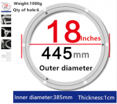
My current one uses one of these waistline training disks as a Lazy Susan bearing between to plates. But I've just ordered this proper Lazy Susan bearing from AliExpress for about 45EUR with shipping. That'll create a new version with overall thinner dimension.
My current one uses one of these waistline training disks as a Lazy Susan bearing between to plates. But I've just ordered this proper Lazy Susan bearing from AliExpress for about 45EUR with shipping. That'll create a new version with overall thinner dimension.
Attachments
I skipped that bearing system and invested on a pack of felt pads as sliders. A coated board is very slippery!
Microwave owens have a roller circle under the glass plate, that can be recycled to diy turtable too. Centering might be difficult.
Make the turntable so big that you can put a kitchen ladder on it to hold a small speaker. Even better to have one under the turtable and second on top of it.
Microwave owens have a roller circle under the glass plate, that can be recycled to diy turtable too. Centering might be difficult.
Make the turntable so big that you can put a kitchen ladder on it to hold a small speaker. Even better to have one under the turtable and second on top of it.
Last edited:
Acoustic center gadget added to rev. 2.0.11.0 (2019-01-21)
Spitting image with simulated test responses
The latest manual may have some useful information about this in addition to political bs statements
Spitting image with simulated test responses
An externally hosted image should be here but it was not working when we last tested it.
The latest manual may have some useful information about this in addition to political bs statements
- Home
- Design & Build
- Software Tools
- VituixCAD