^There is no absolute omni i.e. DI=0.000000... dB above 0 Hz if the radiator is one side only and baffle dimensions > 0 mm. But DI result with Diffraction tool is a bit high at the lowest octaves because just 1st order diffractions are included in the simulation. You can see decrease in SPL and DI by increasing listening distance towards infinity i.e. adjusting direct to diffracted ratio towards 1.0.
P.S. The latest build of 2.0.58.1 (few minutes ago) has adaptive constraint in axial distance. Minimum distance from baffle corner to mic is 100 mm.
P.S. The latest build of 2.0.58.1 (few minutes ago) has adaptive constraint in axial distance. Minimum distance from baffle corner to mic is 100 mm.
Last edited:
Hi Kimmosto,
Today I've completed the assembly of a Najda DSP and a 6x180W hypex amplifier.
I'm asking myself which DSP system I should use in VituixCAD options ?
Nicolas (WAF audio), sadly is missing since 2019, and I don't know how to find the answer. If it can help, I think that the DSP board use a dual-core DSP56725.
Regards,
I don't recall Nicolas ever declaring what filter definitions or biquad formats he had designed Najda to. I had some success using "The Active Crossover Designer" (ACD) spreadsheet from Charlie Laub, which was made for miniDSP, but the problem I had at the time was that filter shapes on the high frequency end were inaccurate. I tried to engage him on this, but I failed get him to address the issue. So, I think you are on your own here when it comes to selecting which DSP option to choose (I am personally interested in knowing the answer).
Some more about this problem in the papers below:
https://bennettprescott.com/downloads/TwoProcessors.pdf
https://bennettprescott.com/downloads/DSP_Differences.pdf
Some more about this problem in the papers below:
https://bennettprescott.com/downloads/TwoProcessors.pdf
https://bennettprescott.com/downloads/DSP_Differences.pdf
^As told few messages earlier, revision 2.0.58 or later cannot read target lines of projects files saved with 2.0.57 or earlier. So you need to:
1) Show target curve with context menu
2) Re-adjust both ends of target line with Shift or Ctrl key pressed + mouse left button + mouse wheel.
3) Save the project.
In addition, target line/curve is possible to configure with Optimizer window with frequency range, SPL and Tilt parameters. Note that you must check modify to show and adjust Power target with Optimizer window.
I have tried to explain this in user manual, but it's a bit fuzzy in the beginning.
I'm asking myself which DSP system I should use in VituixCAD options ?
I don't know much about Najda. DSP selection may depend on how Najda is programmed. DSP selection does not matter if configuration of Najda uses plain biguad coefficients (b0,b1,b2,a1,a2) and coefficients are exactly compatible with miniDSP i.e. a0 is normalized to 1 and sign of a1 and a2 are multiplied by -1 compared to e.g. RJB. Just sample rate matters and you can select for example miniDSP 96k.
In addition, possible prewarping and other special coefficient math for standard slopes such as Bessel, Butterworth and L-R HP/LP could cause compatibility issues.
Unfortunate situation is that I cannot make VituixCAD to emulate all available DSP gears and their configurators.
Kimmo, would it be possible to create a template with variable/selectable parameters for setting up arbitrary DSP configurations? One that the user can tweak until the appropriate settings are determined for their specific DSP. Then the user can save that as a unique configuration.
Would entail setting up a standard/defined filter in the DSP, measuring the response and comparing it to the expected transfer function. If the difference can be parameterised, then the resultant data might be used to define the configuration specific to the DSP. Might require a set of tests.
Would entail setting up a standard/defined filter in the DSP, measuring the response and comparing it to the expected transfer function. If the difference can be parameterised, then the resultant data might be used to define the configuration specific to the DSP. Might require a set of tests.
I don't recall Nicolas ever declaring what filter definitions or biquad formats he had designed Najda to. I had some success using "The Active Crossover Designer" (ACD) spreadsheet from Charlie Laub, which was made for miniDSP, but the problem I had at the time was that filter shapes on the high frequency end were inaccurate. I tried to engage him on this, but I failed get him to address the issue. So, I think you are on your own here when it comes to selecting which DSP option to choose (I am personally interested in knowing the answer).
Some more about this problem in the papers below:
https://bennettprescott.com/downloads/TwoProcessors.pdf
https://bennettprescott.com/downloads/DSP_Differences.pdf
Thanks you for your response. I think I will monitor the outputs with REW to compare the result with vituixCAD.
My guess is that miniDSP will be fine.
I don't know much about Najda. DSP selection may depend on how Najda is programmed. DSP selection does not matter if configuration of Najda uses plain biguad coefficients (b0,b1,b2,a1,a2) and coefficients are exactly compatible with miniDSP i.e. a0 is normalized to 1 and sign of a1 and a2 are multiplied by -1 compared to e.g. RJB. Just sample rate matters and you can select for example miniDSP 96k.
In addition, possible prewarping and other special coefficient math for standard slopes such as Bessel, Butterworth and L-R HP/LP could cause compatibility issues.
Unfortunate situation is that I cannot make VituixCAD to emulate all available DSP gears and their configurators.
Thanks you for the informations.
I totally understand the dfficulty of implementing all DSP gear
")
I will give you the answser in the next few weeks I hope
Member
Joined 2003
^I can try but chances are close to zero if the file saved with Save IR button is binary file. Other than txt formats are not documented in user manual so any kind of 'reverse engineering' is not desirable I guess. I don't see why Bodhan would help us privately.
You can send zip file including file saved with Save IR button, and exported with 'Export norm' button as txt and wav with normalisation factor 1.0 that I can compare files and results.
P.S. I also have some very old SE but file format has probably changed.
You can send zip file including file saved with Save IR button, and exported with 'Export norm' button as txt and wav with normalisation factor 1.0 that I can compare files and results.
P.S. I also have some very old SE but file format has probably changed.
Last edited:
Kimmo, would it be possible to create a template with variable/selectable parameters for setting up arbitrary DSP configurations?
'DSP system' combo box was added to rev 2.0.5.2 (2018-10-09) but program still has three internal switches for DSP features:
- Active PEQ response as analog RLC (Q factor is compatible with analog RLC)
- Bessel phase normalized (filter order defines phase angle at corner frequency, gain is not constant -3 dB)
- Shelving frequency at middle gain (gain is max gain / 2 in dB at corner frequency)
So in theory there are only eight possibilities in addition to different sample rates.
I could also add two new switches to Options window:
- uninverted sign for a1 and a2
- not normalized a0
to support some other than miniDSP if user transfers parameters as plain/raw biquad coefficients.
But that's almost all I could do without full documentation from DSP manufacturers. So far I have asked calculation spec from Hypex which is using proprietary prewarping i.e. math which tries to emulate analog equivalent and produce ideal textbook response as close to fs/2 as possible. Documentation did not exist and was not sent to me so VituixCAD cannot show exactly correct response with any Hypex DSP. Situation would be much worse with e.g. Lake because their PEQ and shelfs are not standard. Manufacturers probably think that their filter designer application (with some special math) is the best or at least adequate for this job. But it's not in my opinion. I would not buy DSP products which can not follow known standards and do not contain documentation for non-standard features.
Last edited:
Member
Joined 2003
^I can try but chances are close to zero if the file saved with Save IR button is binary file. Other than txt formats are not documented in user manual so any kind of 'reverse engineering' is not desirable I guess. I don't see why Bodhan would help us privately.
You can send zip file including file saved with Save IR button, and exported with 'Export norm' button as txt and wav with normalisation factor 1.0 that I can compare files and results.
P.S. I also have some very old SE but file format has probably changed.
Great, you've got mail!
^Received, thanks. RES file looks hopeless because it's binary. Exported txt file has just time series without information about sample rate or interval. Number of samples equals to number of rows.
At the moment exported txt file is readable as MLSSA txt after the following three lines are added to the beginning with some text editor:
0
0.010416666666666667
262143
2nd line is sampling interval in milliseconds. So the easiest mod to the program would be asking sample rate and counting rows if the first line is not " 0".
Attachments
Member
Joined 2003
Thanks so much for having a look, and the addition sounds good to me. My only other suggestion may be a prompt for "multiplication factor" on import to account for any IR files that may have been exported without using a normalization coefficient of 1.0.
The key factor with SoundEasy is to keep track of recorded sampling rate and and to make sure you always set the export normalization coefficient to 1.0. By default SE will automatically set the coefficient to the value at the peak of the impulse, so the maximum value of the exported data is 1.0. I'm at a loss to determine any benefit that this coefficient provides.
The key factor with SoundEasy is to keep track of recorded sampling rate and and to make sure you always set the export normalization coefficient to 1.0. By default SE will automatically set the coefficient to the value at the peak of the impulse, so the maximum value of the exported data is 1.0. I'm at a loss to determine any benefit that this coefficient provides.
^Small improvement done.
2.0.58.2 (2020-12-07)
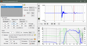
Convert IR to FR
* Program asks sample rate and counts data rows if loaded text file does not contain header rows of MLSSA txt format.
2.0.58.2 (2020-12-07)
Convert IR to FR
* Program asks sample rate and counts data rows if loaded text file does not contain header rows of MLSSA txt format.
Last edited:
Hi,
I am a new user of the program and I think it is cool. I'm sorry if I am asking a question that's been asked before. Just wanted to know how does one quickly simulate the magnitude and phase responses of electrical filters (mostly active crossovers) without any drivers connected. A manual page reference would be great too. Thanks a mil.
I am a new user of the program and I think it is cool
. I'm sorry if I am asking a question that's been asked before. Just wanted to know how does one quickly simulate the magnitude and phase responses of electrical filters (mostly active crossovers) without any drivers connected. A manual page reference would be great too. Thanks a mil.- Home
- Design & Build
- Software Tools
- VituixCAD