Hello.
I have long thought about the idea of using my spare time to improve existing models of popular devices such as the BCxxx series.
My first attempt were the 2N5769/5771. The 5769 model was faulty in that it was the exact same model used for the 2N5772 (if I remember correctly), and thus had an optimum bias of about 10mA instead of the 2mA on the datasheet.
Here are the datasheets. They are not for the specific devices, but they are what the original datasheets refer you to if you want to see the characteristics. If I'm to trust them, the 5769/5771 pair is fairly complementary, which makes them highly desirable if you're making some kind of superfast circuitry.
http://www.fairchildsemi.com/ds/PN/PN2369A.pdf
http://www.datasheetcatalog.org/datasheets/208/456699_DS.pdf
Here are the original models:
.model Q2N5769 NPN(Is=44.14f Xti=3 Eg=1.11 Vaf=100 Bf=78.32 Ne=1.389
+ Ise=91.95f Ikf=.3498 Xtb=1.5 Br=12.69m Nc=2 Isc=0 Ikr=0 Rc=.6
+ Cjc=2.83p Mjc=86.19m Vjc=.75 Fc=.5 Cje=4.5p Mje=.2418 Vje=.75
+ Tr=1.073u Tf=227.6p Itf=.3 Vtf=4 Xtf=4 Rb=10)
* National pid=21 case=TO92
* 88-09-07 bam creation
*$
.model Q2N5771 PNP(Is=545.6E-18 Xti=3 Eg=1.11 Vaf=100 Bf=76.77 Ne=1.5 Ise=0
+ Ikf=50m Xtb=1.5 Br=1.365 Nc=2 Isc=0 Ikr=0 Rc=3.75 Cjc=2.77p
+ Mjc=.1416 Vjc=.75 Fc=.5 Cje=2.65p Mje=.3083 Vje=.75 Tr=4.033n
+ Tf=118.5p Itf=.5 Vtf=3 Xtf=6 Rb=10)
* National pid=65 case=TO92
* 88-09-08 bam creation
And here are my models. The Hfe curves fit the datasheet values better than the old ones did. Someone told me there was something wrong, but never explained why. The curves match the datasheet, I don't see what could be wrong.
.model 2N5769 NPN(Is=44.14f Xti=3 Eg=1.11 Vaf=100 Bf=78.32 Ne=1.389
+ Ise=91.95f Ikf=50m Xtb=1.5 Br=1.365 Nc=2 Isc=0 Ikr=0 Rc=.6
+ Cjc=2.83p Mjc=86.19m Vjc=.75 Fc=.5 Cje=4.5p Mje=.2418 Vje=.75
+ Tr=1.073u Tf=227.6p Itf=.3 Vtf=4 Xtf=4 Rb=10 Vceo=15 Icrating=200m mfg=Fairchild)
.model 2N5771 PNP(Is=44.1f Xti=3 Eg=1.11 Vaf=100 Bf=76.77 Ne=1.389 Ise=91.95f
+ Ikf=50m Xtb=1.5 Br=1.365 Nc=2 Isc=0 Ikr=0 Rc=3.75 Cjc=2.77p
+ Mjc=.1416 Vjc=.75 Fc=.5 Cje=2.65p Mje=.3083 Vje=.75 Tr=4.033n
+ Tf=118.5p Itf=.5 Vtf=3 Xtf=6 Rb=10 Vceo=15 Icrating=200m mfg=Fairchild)
As you can see, I borrowed parameters between the models, but didn't change the AC characteristics any. I have similar models for the BC557C/547C I made, if some one is interested.
- keantoken
keantoken,
Transistor parameters for a particular type device vary widely, and those that are given are often typical or worst case. For example, the current gain of the 2N2369A can vary from 40 to 120 at 10 mA. Other parameters (Tf, for example) will also have wide variations. So it is incorrect to assume that a SPICE model accurately describes all of the devices of a particular type; it does not!
So what do you do about it? You design your circuits so that they will meet their specifications, despite parameter variations. Good circuits should be relatively insensitive to parameter variations. In your Allison circuits do you really care how Bf varies with Ic? I know you care about Vbe, but Vbe is directly related to Is and Is is one of those parameters that varies widely. (You should study the effects of parameter variations.)
As for your specific questions, I would leave the models as they are. I don't know why you think the 2N5769 and 2N5771 are complements, and I don't even know what 'complementary' transistors means. I would also like to point out that Br effects storage time (Ts), because:
Ts=Tr*Br/1.7
Br has no real effect when the transistor is in the active region. Also different values of Bf and Tr can give the same storage time.
Rick
keantoken,
So what do you do about it? You design your circuits so that they will meet their specifications, despite parameter variations. Good circuits should be relatively insensitive to parameter variations. In your Allison circuits do you really care how Bf varies with Ic? I know you care about Vbe, but Vbe is directly related to Is and Is is one of those parameters that varies widely. (You should study the effects of parameter variations.)
Br has no real effect when the transistor is in the active region. Also different values of Bf and Tr can give the same storage time.
Rick
I DO design my circuits WRT variations... AFAIK I haven't posted stupid circuits in that regard for some time now (but I would be glad if you pointed them out).
Consider this: a precision amplifier will have high NFB factor, making the variations of each individual component not that bothersome. But what if we tone down (or turn off) NFB to try and reduce high-order harmonics? Then the individual device characteristics become more important. Everything is a compromise, and the better models we have, the more realistic our simulations (though I agree we should not at all rely on the simulator or expect it to be spot-on).
I had no intention of messing with anything but the Bf/Ic/Vbe curves, so it was a mistake for me to change Br.
Here are my preliminary prerequisites for a VAS transistor:
1: Hfe linearity: what Ic is the highest bias point (crest of Hfe curve). If we drive the VAS beyond this point, we will inject odd order and beyond harmonics into the NFB loop.
2: Cob. Faster transistors will reduce THD20. Smaller Cob will have a smaller Varactor effect.
3: Hfe to transconductance ratio (IE ratio of base current to how much AC I will waste through B-E resistor due to Vbe variation). High Hfe scores better here.
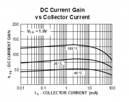
With this taken into consideration, the original 5769 model does not meet my criteria for being very accurate to the actual device if used as a VAS. Gain is expected to crest at 2ma, and even with respect to component variations a 10ma figure for this is just not realistic (or maybe things are worse than I imagined?).
So, my models are very approximate. Values shown in the datasheet are typical, which means I guess they are the average of a selection of tested devices. I fitted to those datasheet curves, so I should have models of "typical/average" devices.
In light of this, Is there something more specific you can say that makes my (albeit rednecked) work on the 5769 model as unnecessary as you seem to be saying?
It would be nice to have a curve tracer.
- keantoken
First, let me address your 2N5769 model. Reducing Ikf reduces the value of Ic where the (high) current gain rolls off, and Ikf of 50m makes this too low. You can see this effect by plotting Ic/Ib vs. log(Ic). I think the original model is better in this respect. According to the data sheet you referenced, Ic is nearly constant from 1 to 10 mA.
Regarding typical values on the data sheet. When I was a young engineer, my boss and I were discussing a circuit I designed. I don't remember any of the circuit details, but he wasn't too happy about some of the values I chose. I said "I used typical data sheet values in my calculations." He said typical means they saw one like it once, but they may never see another one - in other words, typical is meaningless. It's not really that bad, but you should never depend on having typical values to make your circuit meet specifications.
Yes, negative feedback is a way to make circuits less sensitive to device parameter variations. As I have pointed out previously, the Allison circuits have a high open loop gain and a feedback factor of 1.
I'm not worried about the Allison circuit, and it is not the specific reason I chose to look at the 57xx models (although I probably gave that impression). I am more interested in their application as a VAS. If they can be expected to operate no better than the datasheet specifies, then I save myself the trouble of getting optimistic simulations.
I am looking at the models again, but even with the current value of IKF they still look a lot like the datasheet. (Hfe is very low, actually, but the curve is amazingly similar)
I am not sure what you mean when you say Ic is nearly constant from 1-10mA. Hfe crests at 2mA, and though it is quite flat until 10mA, by going past 2mA we've already started injecting strange harmonics (which gets worse since the Hfe of these is very small).
Maybe I'm nitpicking?
- keantoken
Attachments
Okay, I realized a large error with the models, which is the rather low Hfe (much lower then typical values). That should be rather obvious from my last post (eep!). 
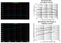
I'm working on correcting this. I keep making that mistake by reading the original graph wrong. Out of boredom I've begun to look at temperature-related effects.
Please understand that this is a learning experience for me, and even if it doesn't make sense to make better models for these devices, I'm gonna do it anyways.
- keantoken
keantoken,
I overlooked the fact that the gain was too low, too. Post your updated model, when you get it the way you want.
If you intend to study the BJT model and temperature effects you should look at: www.intusoft.com/lit/WkwModels.pdf I mentioned this some time ago and your reaction was something like "Boy, that is a lot of stuff.", but this is the best free document I'm aware of that does a good job of covering the BJT model of SPICE. It also covers temperature effects. You should use it for a guide. Actually, it isn't very complicated, but it is a little tedious. Quote from WkwModels: "While these equations and the evaluation of their coefficients appear formidable, you should remember that most applications
will reverse bias the collector-base junction, which effectively
eliminates all terms involving VBC (shaded areas)." Let LTspice do the work for you by using known parameters for your models and have LTspice plot the results. Experiment with different parameters. (Note that the equation TR=.6*Ts on page 34 is wrong. It should be Ts=Tr*Br/1.7.)
This will be a good learning experience, but, again, don't overlook device to device parameter variations. Generally, when I make a model, I go for worst case, and knowing how the BJT model works allows me to do this.
Rick
Okay, here it is (FINALLY).
By pure trial and error (and great patience), I have deduced that:
Adjust Is first, to get Vbe right. Then adjust Eg to get tempco right.
Then move to Ikf.
There are three components I use concerning the Hfe curve:
1: Hfe at top of crest.
2: Ic where Hfe crests.
3: Point between crest and max. Ic where Hfe falls closest to an integer.
4: Slope of Hfe from beginning to crest of graph.
From I deduced that:
1: Crest of Hfe was 85.
2: Ic crests at 2mA.
3: At 30mA Hfe is 70
4: Hfe changes by 15 from 10uA to 2mA.
During my journey I noticed that:
1: A low value of Ikf will make your actual gain much lower that Bf.
2: It is best to choose a good value for Ikf first and then use Ise and Ne to adjust the curve.
3: The difficult part is getting the slop right as well has the Ic crest. To do this you have to change the ration of Ikf to Bf.
I think we call this the Babylonian Method...
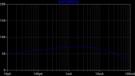
Anyways, here it is. I've attached a comparison between the datasheet and SPICE.
.model 2N5769 NPN(Is=1.2f Xti=3 Eg=1.16 Vaf=100 Bf=88 Rb=45
+ Ikf=200m Ise=33f Ne=1.7 Xtb=1.7 Br=1.365 Nc=2 Isc=0 Ikr=0 Rc=.6
+ Cjc=2.83p Mjc=86.19m Vjc=.75 Fc=.5 Cje=4.5p Mje=.2418 Vje=.75
+ Tr=1.073u Tf=227.6p Itf=.3 Vtf=4 Xtf=4 Vceo=15 Icrating=200m mfg=Fairchild)
The 5771 has the same curve but different Hfe, so I'll have to tweak this model a bit to use it.
- keantoken
By pure trial and error (and great patience), I have deduced that:
Adjust Is first, to get Vbe right. Then adjust Eg to get tempco right.
Then move to Ikf.
There are three components I use concerning the Hfe curve:
1: Hfe at top of crest.
2: Ic where Hfe crests.
3: Point between crest and max. Ic where Hfe falls closest to an integer.
4: Slope of Hfe from beginning to crest of graph.
From I deduced that:
1: Crest of Hfe was 85.
2: Ic crests at 2mA.
3: At 30mA Hfe is 70
4: Hfe changes by 15 from 10uA to 2mA.
During my journey I noticed that:
1: A low value of Ikf will make your actual gain much lower that Bf.
2: It is best to choose a good value for Ikf first and then use Ise and Ne to adjust the curve.
3: The difficult part is getting the slop right as well has the Ic crest. To do this you have to change the ration of Ikf to Bf.
I think we call this the Babylonian Method...
Anyways, here it is. I've attached a comparison between the datasheet and SPICE.
.model 2N5769 NPN(Is=1.2f Xti=3 Eg=1.16 Vaf=100 Bf=88 Rb=45
+ Ikf=200m Ise=33f Ne=1.7 Xtb=1.7 Br=1.365 Nc=2 Isc=0 Ikr=0 Rc=.6
+ Cjc=2.83p Mjc=86.19m Vjc=.75 Fc=.5 Cje=4.5p Mje=.2418 Vje=.75
+ Tr=1.073u Tf=227.6p Itf=.3 Vtf=4 Xtf=4 Vceo=15 Icrating=200m mfg=Fairchild)
The 5771 has the same curve but different Hfe, so I'll have to tweak this model a bit to use it.
- keantoken
Attachments
Last edited:
And here is the accompanying 5771 model.
.model 2N5771 PNP(Is=1.2f Xti=3 Eg=1.16 Vaf=100 Bf=125 Rb=45
+ Ikf=100m Ise=62f Ne=1.7 Xtb=1.7 Br=1.365 Nc=2 Isc=0 Ikr=0 Rc=3.75
+ Cjc=2.77p Mjc=.1416 Vjc=.75 Fc=.5 Cje=2.65p Mje=.3083 Vje=.75 Tr=4.033n
+ Tf=118.5p Itf=.5 Vtf=3 Xtf=6 Rb=10 Vceo=15 Icrating=200m mfg=Fairchild)
The Babylonian Method takes patience at first but it gets SOOOO much easier after you figure out the pattern. I've attached a virtual test fixture you can verify the models with.
The only thing I don't know how to fix for this model is the Hfe behavior at 125C.
I think my old models can be used as "worst case" models, since the Hfe is so low...
- keantoken
Attachments
Last edited:
The BJT default in ISSPICE4 gives first order, Ebers-Moll, DC
parameters; but it does not provide parameters for Transient or
AC analysis. The following default can be used when minimal
data sheet specifications are available by using the PARAM
program to evaluate the equations in curly braces. This model
will create a good transistor model from virtually any data sheet.
The parameters you must specify are:
IMAX Maximum collector current
COB Collector-base capacitance
FT Gain bandwidth product in Hz
TS Storage time
The equation-based model is shown below:
.MODEL NBJT NPN (CJC={2.2*COB} TF={.16/FT} TR={1.7*TS}
+CJE={7*COB} RC={.5/IMAX} VAF=100 IKF={.7*IMAX}
+ IS={2E-15*MAX} )
This subcircuit-based macro model makes use of the default
model parameters so that it is not permissible to change default
values without reevaluating the parameters which are given
here.
I was page-flipping randomly through that PDF and found this.
I suspected at first there was a correlation between Icmax and IKF, but looking through the LTSpice library convinced me otherwise. Not sure about Is.
It would be great if I could figure out some way to shove Ise in there...
More page-flipping will follow.
I would still rather babylize it than figure out all that math (my grandma always said that lazy people work 3 times harder...).
- keantoken
Okay, I think those models are good enough. Here is my current attempt at the BC547C, using this datsheet:
http://www.onsemi.com/pub_link/Collateral/BC546-D.PDF
.model BC547C NPN(Is=32f Xti=3 Eg=1.11 Vaf=100 Bf=720
+ Xtb=1.5 Br=6.313 Isc=138f Nc=2.053 Rb=1.3k
+ Ikf=500m Ise=230f Ne=1.583 Nk=1.05
+ Ikr=.187 Rc=.4216 Cjc=5.25p Mjc=.3147 Vjc=.5697 Fc=.5 Cje=11.5p
+ Mje=.3333 Vje=.5 Tr=10n Tf=410.7p Itf=2.204 Xtf=66.65 Vtf=10)
One question... Isn't Rb a little large?
- keantoken
keantoken,
Do you have a model for the 2SC3503? Fairchild doesn't seem to have it on it's site... I found the complimentary other half of the pair 2SA1381 on their site. Funny...
Thanks,
Ken
Keantoken,
I found them...
So, I know this is off topic, but, was wondering if you could help. I'm using a LME49811 for the front end of my amp - first and second stage - and was looking for a simple way to simulate the third stage including the bais scheme. I found this image from Bob Cordell, but don't know how to get it to work. I've also attached a zip of my model. Any thoughts? I would like to model the bais along with the output stage. I've been able to get the bais model to work by its self and the third stage as well...
Ken
Attachments
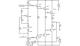
That was interesting. In the VAS, you are applying positive feedback instead of negative feedback (your image is wrong it seems). Try this.
I used different models, so you'll have to change them back.
- keantoken
I'll give it a go later this afternoon. Interesting, the image was from Bob Cordell... maybe wanted to throw neophites like me for a loop.
By the by, one of the things I want to try is driving the allison configuration with the LME49811, do you think it will work?
Thanks again.
Ken
I think it would be great for driving the Allison! You should get great distortion specs... Although the best way to drive the Allison is between the emitters of the bias transistors, you might get lower distortion specs that way.
One thing I should say about the Allison is that there are a billion different ways you can use it, all of which it would take time to document. Feel free to consult me about the Allison, maybe I should draw up all the different schematics and forms I've seen it take and compile into one huge PDF. I wouldn't worry about the sonic qualities of it, the best sound I have ever heard was played with an LTP frontend through an Allison, out of a 3" speaker...
- keantoken
- Status
- This old topic is closed. If you want to reopen this topic, contact a moderator using the "Report Post" button.
- Home
- Design & Build
- Software Tools
- BJT SPICE Models, reality-check