Hi
I finished my amp and the rectifier tube red plates after about 1 minute. Without the tube there is no problem, and all of the Heater/V test correctly, The Bias is -150. I took the choke out and the tube did not red plate for over 5 minutes so I put back the 150 ohm R and then it red plates.
I checked the fets for a short and there is none, there is no misplaced parts or solder bridges. I tried two tubes and it is the same. I sent George a private message but there is no response. I am staring to think that the board has a short in the tracings. Any help would be very much appreciated. Thanking you in advance.
Donald
.I sent George a private message but there is no response
Sorry, internet service here is often useless during the day with everybody inside their homes streaming video. We live two miles from town on a country road. There is no OTA TV or decent cellular coverage, so everybody is using the same cable into town. Your PM email notification looks like it came in Wednesday night or Thursday here and I was out all day yesterday mowing.
My first question was going to be which TSE you have, but I found your board order from 2017, that makes it the "original TSE" so the next question is, is this a new build, or one that once worked, then died?
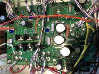
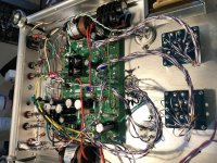
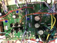
A couple pictures of both sides of the board and the wiring would get more eyes on the problem and often leads to a quicker resolution. Post a few if you can.
I am staring to think that the board has a short in the tracings.
That board remained unchanged from the first one in 2005 until the last in 2019, and there has never been a shorted board that I know of.
Obviously you have a short on the B+ somewhere. Does it measure shorted, or low resistance when tested with an ohmmeter?
With an UNPOWERED board, put one meter lead on the ground (T1-1) pad in the left front corner of the board, and touch the other meter lead to the right hand end of R4 (the 150 ohm resistor). You should have a reading above 5000 ohms.
A low resistance indicates a short. If you have a low resistance, verify that C4 and C5 both have their negative stripe closest to the front edge of the board.
Are the heatsinks grounded? If so there must be insulators on the CCS chips, U2 and U3, otherwise a short will occur.
Disconnect the OPT leads from the board at T2-1 and T3-1. Is the short still there? If so pull the jumper between BPLUSS and DRV_B+ on the board between R18 and R14. Which side of the jumper is the short on?
Hi
Thanks for the response, it is a new build, I get 2M on both sides of r5, the caps are correct . I have insulators on the chips and I checked that they are not grounded to the heat sink, the heat sink is grounded. I
get over 1M ohms on the B+ circuit at the jumper location, I can take a pic of the top side of the board but to do the bottom I have to unsolder all of the remote wires as it is mounted with the tubes off the board in the enclosure. I checked the OPT and they have normal R, The B+ of the opt have approx 2 M ohms at the connection
I also checked the right pin of the fets to the center pin and they are shorted, ( is this normal? ) I bought the fets from Newark and they are an IXYS exact replacement part as I could not get the specified ones.
Donald
I am trying to upload this file however it isn't very user friendly.
Hard to tell from the picture, but the orange wire coming from T32 looks to be cut, and one free end is embedded in the purple wire.
You have a lot going on with that build. The safer practice is to build it the way it is supposed to be built, and make sure it works the way it is supposed to work, before deviating from the norm.
The 5842's may not like those long leads between the board and wherever the tube is.
Hi
Do you mean T2-2? Anyway it is not cut, it is curled around itself because of it's length, I try keep the wires of the L&R signal circuit the same length, that is why I didn't cut it to fit.
Why would the wires extension be a problem for the 5842, they are not any longer than if it was a point to point, I wanted the tubes in the top of the enclosure so with this board there was no other choice.
Do you know the answer to my question about the fets? I can not find the short from any area of the B+ circuit so I am left with two options , the board tracing or the fets, George has stated that it is doubtful that the board has a problem.
Thanks for your time.
Donald
This is what we have to go on.
The rectifier tube red plates on power up. I am assuming that this is with no other tubes installed.
The rectifier tube does not red plate if the choke is disconnected. This implies that the problem is downstream from the choke / R4. Did B+ voltage appear on C4 when the choke was disconnected? Measure voltage from ground to the R4 pad closest to the left edge of the board, or either yellow power transformer wire. Please note that there is no bleeder resistor in the circuit to discharge C4 when the choke is disconnected. C4 will remain charged for some time after making this test.
You get 2M on either side of R4. This does not make sense since R30 is connected from one end of R4 to ground. You have a 120K or 130K resistor here, so the resistance should be 130K or less. Whenever making a resistance measurement on a circuit containing large capacitors you should try reversing the meter leads to see if you get different readings. If the reading is over 150K both ways then you have another problem.
Maybe. Assuming you are measuring between the right and center pins while looking at the face of the part, you are measuring from the source to the drain. All modern mosfets have an inherent diode built into the structure. You are measuring this diode, so the resistance should be different if the meter leads are switched.
Regardless, the fets are NOT the reason for the red plate on the rectifier. The fet can be totally shorted in every direction, there is still no path for enough current flow to cause a red plate rectifier. There is something else wrong.
The TSE was designed over 15 years ago, and the 2SK2700 went extinct long ago. Far better mosfets have come and gone since then, as technology improves. The users of this forum continually try new parts. There are dozens of good fet choices today, but a few important specs need to be observed. The most important is that it has an internal gate protection Zener. What part did you put in your board?
You stated in your PM that you used the "specified Hammond TX." I see what looks like a Hammond 274BX label in your pictures. That is one of the recommended choices for the SSE amp which runs at B+ voltages far in excess of 400 volts. Some users report over 450 volts in high line voltage environments and that's in the hungrier SSE amp. This is too much B+ for the TSE, and may be causing one of the 450 volt electrolytics to fail. 450+ volts is too much for a 300B and will put too much heat into the mosfets as well.
Try disconnecting C5 and seeing if the problem remains.
The 5842 is a very high Gm (gain) tube. It was originally intended for high frequency telephone repeaters, so it is capable of operating at ultra high frequencies, and has a reputation for oscillating if given the slightest chance. The WE-417 / 5842 and their cousins like the German D3A have indeed been used successfully in point to point wired applications, but many more DIY builders have failed to make successful amps with them than successful ones. Those that have succeeded have used very short (under 1 inch) wires and multiple grid stopper resistors directly on the tube pins.
In this case the high Gm tube is run at maximum gain by the combination of a high Gm CCS load ( the IXYS chip) and a high Gm Mosfet buffer. The TSE, and now TSE-II boards went through multiple design passes to get this area correct, and my day job for 41 years involved designing PC boards for cell phones and other radio frequency devices.
Most builders put the parts on the bottom side of the board and leave the tube sockets on the top such that the board can be mounted about a half inch below the top plate such that the tops of the tube sockets are flush with the surface of the top plate.
I have seen extension wires used on the output and rectifier tubes, but they also must be kept short, under 3 inches or so.
The rectifier tube red plates on power up. I am assuming that this is with no other tubes installed.
The rectifier tube does not red plate if the choke is disconnected. This implies that the problem is downstream from the choke / R4. Did B+ voltage appear on C4 when the choke was disconnected? Measure voltage from ground to the R4 pad closest to the left edge of the board, or either yellow power transformer wire. Please note that there is no bleeder resistor in the circuit to discharge C4 when the choke is disconnected. C4 will remain charged for some time after making this test.
I can not find the short from any area of the B+ circuit
You get 2M on either side of R4. This does not make sense since R30 is connected from one end of R4 to ground. You have a 120K or 130K resistor here, so the resistance should be 130K or less. Whenever making a resistance measurement on a circuit containing large capacitors you should try reversing the meter leads to see if you get different readings. If the reading is over 150K both ways then you have another problem.
I also checked the right pin of the fets to the center pin and they are shorted, ( is this normal?.....Do you know the answer to my question about the fets?
Maybe. Assuming you are measuring between the right and center pins while looking at the face of the part, you are measuring from the source to the drain. All modern mosfets have an inherent diode built into the structure. You are measuring this diode, so the resistance should be different if the meter leads are switched.
Regardless, the fets are NOT the reason for the red plate on the rectifier. The fet can be totally shorted in every direction, there is still no path for enough current flow to cause a red plate rectifier. There is something else wrong.
I bought the fets from Newark and they are an IXYS exact replacement part
The TSE was designed over 15 years ago, and the 2SK2700 went extinct long ago. Far better mosfets have come and gone since then, as technology improves. The users of this forum continually try new parts. There are dozens of good fet choices today, but a few important specs need to be observed. The most important is that it has an internal gate protection Zener. What part did you put in your board?
You stated in your PM that you used the "specified Hammond TX." I see what looks like a Hammond 274BX label in your pictures. That is one of the recommended choices for the SSE amp which runs at B+ voltages far in excess of 400 volts. Some users report over 450 volts in high line voltage environments and that's in the hungrier SSE amp. This is too much B+ for the TSE, and may be causing one of the 450 volt electrolytics to fail. 450+ volts is too much for a 300B and will put too much heat into the mosfets as well.
Try disconnecting C5 and seeing if the problem remains.
Why would the wires extension be a problem for the 5842, they are not any longer than if it was a point to point,
The 5842 is a very high Gm (gain) tube. It was originally intended for high frequency telephone repeaters, so it is capable of operating at ultra high frequencies, and has a reputation for oscillating if given the slightest chance. The WE-417 / 5842 and their cousins like the German D3A have indeed been used successfully in point to point wired applications, but many more DIY builders have failed to make successful amps with them than successful ones. Those that have succeeded have used very short (under 1 inch) wires and multiple grid stopper resistors directly on the tube pins.
In this case the high Gm tube is run at maximum gain by the combination of a high Gm CCS load ( the IXYS chip) and a high Gm Mosfet buffer. The TSE, and now TSE-II boards went through multiple design passes to get this area correct, and my day job for 41 years involved designing PC boards for cell phones and other radio frequency devices.
I wanted the tubes in the top of the enclosure so with this board there was no other choice.
Most builders put the parts on the bottom side of the board and leave the tube sockets on the top such that the board can be mounted about a half inch below the top plate such that the tops of the tube sockets are flush with the surface of the top plate.
I have seen extension wires used on the output and rectifier tubes, but they also must be kept short, under 3 inches or so.
Answers;
"I am assuming that this is with no other tubes installed."
Yes
"R4 pad closest to the left edge of the board, or either yellow power transformer wire."
B+ 512
"You get 2M on either side of R4."
switched the leads and get 110 K on the R and in The M on the left
"Assuming you are measuring between the right and center pins while looking at the face of the part,"
Yes I used the diode function and it shows a short with leads switched, I also drained the fet before testing
This is the one that I used STMicroelectronics STP9NK90Z
"You stated in your PM that you used the "specified Hammond TX."
I bought that TX because I read the wrong instruction on your site, I realized the mistake and ordered the correct one which is three weeks out, I decided to install this one for testing. C4 is the only cap that has seen the high V so far and only for less than a minute.
"Try disconnecting C5 and seeing if the problem remains."
I will do this later this evening
"Most builders put the parts on the bottom side of the board and leave the tube sockets on the top such that the board can be mounted about a half inch below the top plate such that the tops of the tube sockets are flush with the surface of the top plate.
I have seen extension wires used on the output and rectifier tubes, but they also must be kept short, under 3 inches or so."
The problem is that the enclosure was already punched so that would not work, I can get them to about 6 inches but no less, I will have to try and see if a problem occurs. Do you think that might be OK?
Donald
Last edited:
Problem found
I used my variac to cut the house Volts to 100 so that I get B + 420
With the DRV- B+ jumper cut no change.
OPT leads removed no change
C 5 removed no more red plate
I put everything back except C5 no red plate
I used Mundorf audio grade M-Lytics and they were wired correctly, why do they cause this problem. They are supposed to work the same as an E-lytic.
I checked all of the B+ V and they are now correct, I think that there is a problem with the bias, I get 286 B- off of R6 the schematic says 150 B-
I am still confused as to why the fets read as a short.
Donald
... Why would the wires extension be a problem for the 5842, they are not any longer than if it was a point to point ...
Wires that long in a point to point build would be a bad practice.
Any time you deviate from the way the designer intended the product to be built, you are conducting an experiment. Which is fine if that is what you want to do and can live with the outcome ( some end really badly ). It's an opportunity to learn ( including what won't work ). The best way to do that is to build something the way it is supposed to be built, verify that it works correctly, and then make your changes one at a time, and observe / analyze the results. You have a lot of experiments going on here, all at the same time.
Some of them are simple - you have changed the coupling capacitor value ( my recollection is that it is supposed to be 0.22 uF ). The coupling capacitor capacity and grid resistance of the output tube combine to form a high pass RC filter. You have lowered the corner frequency of that filter; that may be good, bad, or inconsequential depending on your specific setup.
Some of them are significant - for example, the wrong power transformer, the extensions for the tube sockets, filter cap, coupling capacitors, etc. Some of these deviations might be able to be sorted out, and not compromise the performance of the amp, some of them might not.
You're in the middle of all of these simultaneous experiments. It can be really difficult to troubleshoot people through an experiment, so there will not be as many people that are able / willing to help you as there would be with a stock build.
... I can get them to about 6 inches but no less, I will have to try and see if a problem occurs. Do you think that might be OK? ...
For the 5842's, not likely, for the reasons stated about the fundamental characteristics of the device. Fooling around with these things is looking for trouble. My gut feeling is that they will be highly unstable and this is something that is very unlikely to be successfully sorted out, and you would need some test equipment to determine success or failure in any event. Bolder builders may have a different opinion, but this is mine. You say this is necessary to mount the board in your chassis, which looks robust and expensive - I don't know that there is an easy solution to this problem. Hopefully someone else will have one.
I used ... audio grade M-Lytics and they were wired correctly, why do they cause this problem. They are supposed to work the same as an E-lytic.
"Audio grade" is the first clue, what exactly does that mean? Mass produced capacitors from mainstream manufacturers have uniform characteristics, are of high quality, and give a long service life. It's possible to get a new, but bad, part, but it has only happened to me once. Money spent on output transformers pretty much gets you what you paid for. Capacitors don't. Save the fancy capacitor money and spend it on the transformers. BTW, those coupling capacitors, if they are the paper in oil type, are already known in this sub forum to be troublemakers.
I hope this does not come across disrespectful or rude - it's not meant to be. None of us are born knowing this stuff, we all have to learn it somehow or someway. There is a lot of knowledge in this subforum, and it is a great place to learn.
Rectifier red plate
Hi
There is no disrespect taken in your replies as I am happy to get them.
The Mundorf E-Lytic was indeed shorted, so with the Nichicon in C-5 the red plate issue went away. BTW Mundorf is a very highly regarded capacitor mgf.
The coupling caps Per a response to someone else from George that I read on this web site can be from .1 to 1 UF my set up for this amp is to have freq. from 2100 hz to 5000 hz for my mid bass horns in a multi amp system. The OPT are wound and air gapped specifically for this. Yes, they are the Mi-flex paper and oil a cheaper alternative to Dueland. I have used them three times and have never had a problem.
The Power TX. I bought in error because I read the wrong paper on the website not realizing that this board was discontinued and there was a second one. As I stated the correct TX is still two weeks away so I am using a variac just for testing purposes.
I can not put the tubes on board with this enclosure, I have done this multiple times with other pre-amp tubes and never had a problem but now I understand that these are highly susceptible to oscillation. So I am where I am, the best that I can do is get the wires to within 6 inches and use grid stoppers, maybe you can help me with this question, Should I move the existing grid stoppers or add to them for the extra six inches?
I don't see where I complicated the amp with the build, all that I did was move the tubes and add some boutique parts, I did not change values unless I read what George said about the coupling caps in error and in fact he also said that C-5 would be a part to upgrade for the best value along with the TX's so I did all three of those.
Do you have a thought as to why my bias volts are at -250 with A/C now at 325 v the specified V for this amp, is it because there is no load? or do I have another problem?
Donald
Last edited:
coupling caps
you have changed the coupling capacitor value ( my recollection is that it is supposed to be 0.22 uF ). The coupling capacitor capacity and grid resistance of the output tube combine to form a high pass RC filter. You have lowered the corner frequency of that filter; that may be good, bad, or inconsequential depending on your specific setup.
Quote;Per George;
The value of the coupling cap is not critical. If you go below 0.1 uF you may lose some bass response. Values above 1.0 uF will cause the bias adjustments to react slowly. 0.22 uF to 0.47 uF are ideal and I have used both depending on availability. The voltage rating should be 450 volts or higher.
I have not tried any Teflon caps, but some builders report good results.
__________________
Tubelab, I blow stuff up so that you don't have to.
Your high negative voltage is NOT a problem. The -150 volt number on my schematic was posted back when the TSE was intended for and most often used with 45 tubes, which could be found on Ebay for $10 each at the time.
You should now be able to stick a voltmeter on the grid terminal of the 300B socket and adjust the voltage on the grid from some low negative voltage (-20 or -30 volts) to a larger negative voltage, -100 volts or so. Do not install output tubes until this works.
Increasing the value of the coupling cap will move the low frequency corner frequency down. This is usually only a problem when there is sufficient low frequency energy in the source, and a smallish OPT. The low frequency energy can hit the OPT and cause saturation.
This implies an active crossover ahead of the TSE, if so, there is no low frequency energy reaching the TSE, so no problem. One of my TSE's has 1 uF caps in it because I have a bunch of Wonder Caps, which were trendy a long time ago.
The mosfets you chose have a rather high reverse transfer capacitance at 40 pF. The 5842 will be driving this capacitance directly. In a typical TSE build with all the parts on the board I would say that this is bad, too much capacitance can roll off the highs, but a typical TSE is limited only by the OPT in the high frequency response.
Your extension wires create a new variable in the "experiment" that is hard to predict. The 40 pf mosfet is on the end of a long wire connected to the 5842's plate. This wire has inductance. The grid of the 5842 is connected to a similar wire in the same bundle creating a coupling capacitor, and some inductance. If a combination of all of these stray capacitance and inductance can create a 180 degree phase shift ANYWHERE in the 5842's audio to 400 MHz range, you have the conditions for oscillation.
That 40 pF mosfet may actually help kill oscillation, but it may also cause it. The mosfet of choice today is the STF3LN80K5. It is about 1 pF.
Once the bias pots are successfully controlling the grid voltage on the 300B sockets, it's time to put the 5842's in the sockets and attempt to set the plate voltage to about 175 volts. The voltage should gradually change as the pot is turned. If it jumps suddenly or will not hold steady particularly as you move your hand or something metallic near the glass part of the tube (top of chassis) the tube is probably oscillating.
I usually test new designs with an RF spectrum analyzer that covers from audio to a couple GHz, but these are not common tools for the DIYer, so there are some low cost alternatives. Find an AM radio and tune it to a weak station near the upper end of the dial. Set it near the amp during this procedure. If the radio starts acting funny (weird sounds, squealing, total silence, humming....) and this goes away when the amp is shut off, your amp is oscillating. If you have a portable TV that works with an indoor antenna, try it near the amp with the weakest channel you can reliably receive. If the amp affects the TV in any way, it is likely oscillating. The TV was my go to test back in the analog TV days but modern digital TV is more immune to it, so it's not as good of a test.
I would go with one on each end of your grid extension wire. Any carbon composition resistor from 2K to 10 K total should work fine. If oscillation is a problem, my next step would be to replace the grid extension with a piece of thin shielded cable. I would experiment with grounding at each end, or both ends to see what works best. If you don't have shielded cable, try some tightly twisted pair. Still oscillates? try using shielded cable for the plate lead.
You should now be able to stick a voltmeter on the grid terminal of the 300B socket and adjust the voltage on the grid from some low negative voltage (-20 or -30 volts) to a larger negative voltage, -100 volts or so. Do not install output tubes until this works.
Increasing the value of the coupling cap will move the low frequency corner frequency down. This is usually only a problem when there is sufficient low frequency energy in the source, and a smallish OPT. The low frequency energy can hit the OPT and cause saturation.
my set up for this amp is to have freq. from 2100 hz to 5000 hz for my mid bass horns in a multi amp system.
This implies an active crossover ahead of the TSE, if so, there is no low frequency energy reaching the TSE, so no problem. One of my TSE's has 1 uF caps in it because I have a bunch of Wonder Caps, which were trendy a long time ago.
The mosfets you chose have a rather high reverse transfer capacitance at 40 pF. The 5842 will be driving this capacitance directly. In a typical TSE build with all the parts on the board I would say that this is bad, too much capacitance can roll off the highs, but a typical TSE is limited only by the OPT in the high frequency response.
Your extension wires create a new variable in the "experiment" that is hard to predict. The 40 pf mosfet is on the end of a long wire connected to the 5842's plate. This wire has inductance. The grid of the 5842 is connected to a similar wire in the same bundle creating a coupling capacitor, and some inductance. If a combination of all of these stray capacitance and inductance can create a 180 degree phase shift ANYWHERE in the 5842's audio to 400 MHz range, you have the conditions for oscillation.
That 40 pF mosfet may actually help kill oscillation, but it may also cause it. The mosfet of choice today is the STF3LN80K5. It is about 1 pF.
Once the bias pots are successfully controlling the grid voltage on the 300B sockets, it's time to put the 5842's in the sockets and attempt to set the plate voltage to about 175 volts. The voltage should gradually change as the pot is turned. If it jumps suddenly or will not hold steady particularly as you move your hand or something metallic near the glass part of the tube (top of chassis) the tube is probably oscillating.
I usually test new designs with an RF spectrum analyzer that covers from audio to a couple GHz, but these are not common tools for the DIYer, so there are some low cost alternatives. Find an AM radio and tune it to a weak station near the upper end of the dial. Set it near the amp during this procedure. If the radio starts acting funny (weird sounds, squealing, total silence, humming....) and this goes away when the amp is shut off, your amp is oscillating. If you have a portable TV that works with an indoor antenna, try it near the amp with the weakest channel you can reliably receive. If the amp affects the TV in any way, it is likely oscillating. The TV was my go to test back in the analog TV days but modern digital TV is more immune to it, so it's not as good of a test.
Should I move the existing grid stoppers or add to them for the extra six inches?
I would go with one on each end of your grid extension wire. Any carbon composition resistor from 2K to 10 K total should work fine. If oscillation is a problem, my next step would be to replace the grid extension with a piece of thin shielded cable. I would experiment with grounding at each end, or both ends to see what works best. If you don't have shielded cable, try some tightly twisted pair. Still oscillates? try using shielded cable for the plate lead.
... my set up for this amp is to have freq. from 2100 hz to 5000 hz for my mid bass horns in a multi amp system ...
In that instance, since you have no need to amplify low frequencies, you might want to consider a significantly smaller value coupling capacitor so that your amplifier power is not wasted on frequencies you don't need. Here is a simple calculator:
High Pass Filter Calculator
.... So I am where I am ...
Well, try it and see. Do you have any test equipment and a dummy load? I would not hook it up to good speakers. Test it on crap speakers so that if they get blown, no big deal.
George was a practicing RF engineer at one of the very best radio manufacturers in the world. IF it can be done, he is the guy that could credibly give you some tips as to the direction(s) to try to take, to maybe make it work. I'm just a tinkerer, and not very good at that. So, I'm not the right person to be helping you with this.
The good thing I see about this situation is that with leads that long, problems will likely be at relatively low frequencies, and probably easier to test for and "fix". And you only need 3 KHz bandwidth, so that might be leveraged as part of a fix, if needed. If I had to do it, I would put the resistors as close to the tube pin as I could, but your sockets really don't permit this - they need radio type sockets, but you've got audiophile type sockets. I would probably consider liberal use of ferrite beads, and I would try to route the wires where my grid and plate leads were as separated as possible. The 5842 is on a nine pin socket, so it can use four separate pins to the grid. I think I would consider using only one grid lead in this circumstance.
Sorry to be negative about this. Hopefully it will work OK. It just looks problematic to me.
- Status
- This old topic is closed. If you want to reopen this topic, contact a moderator using the "Report Post" button.
- Home
- More Vendors...
- Tubelab
- Tube lab Se rectifier tube red plates