I use an active c/o which solves the issue of what Freq. that the amp sees. No low freq. will be presented to it.
In that instance, since you have no need to amplify low frequencies, you might want to consider a significantly smaller value coupling capacitor so that your amplifier power is not wasted on frequencies you don't need. Here is a simple calculator:
High Pass Filter Calculator
No low freq. will be presented to it.
In this case the electrical value of the cap is not a big issue. The problem I see is again the long wires leading to them. A smaller value cap on the board might be a weapon to use if oscillation is an issue.
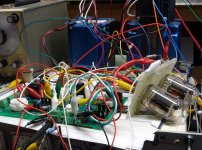
It's easy to look at this and say it won't work, and that would be my logical first assumption. I however have been fooled before by stuff that "will not work." I have been told several times that you can't make a working amp with clip leads connecting everything up......yet this furball of wires worked on the first try and proved completely stable. It was the prototype for this little amp.
Another possibility, and one that may prove to be the easiest choice if the active crossover provides enough output, and the amp doesn't need to be driven into clipping, is to swap the 5842 for another lower Gm tube. This is not an option on the PC board since the 5842 has a unique pinout. Here we have wires going to a socket, so anything goes.
Attachments

Grid stoppers
Hi
Since 4&5 7&8 are connected in the tube should I only run one wire from pin 4 in a shielded cable and not run 5.7.8?
I would go with one on each end of your grid extension wire. Any carbon composition resistor from 2K to 10 K total should work fine. If oscillation is a problem, my next step would be to replace the grid extension with a piece of thin shielded cable. I would experiment with grounding at each end, or both ends to see what works best. If you don't have shielded cable, try some tightly twisted pair. Still oscillates? try using shielded cable for the plate lead.[/QUOTE]
Since 4&5 7&8 are connected in the tube should I only run one wire from pin 4 in a shielded cable and not run 5.7.8?
That's where I would start.
Some DIYers who successfully PTP wired a 5842 claim that running a stopper resistor from each grid pin together as close to the tube as possible, then running one wire from this common connection to the circuit. Obviously each resistor would need to be 4 X the desired value since all 4 would be in parallel.
I have never tried to PTP wire a 5842, so I have no real experience to draw on.
Update; Thanks to George and w5jag
Finally got the correct TX, well actually it is 300 V instead of 320 V ( I would have had to wait until august for the spec) but it still gives me close to 400 V. I powered it up and attempted to set the 417a to 175 V and they would not adjust, the 300 B adjusted perfectly.
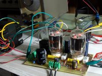
I then separated the long leads feeding the 417A into mid air with plenty of space around them and they adjusted perfectly. I then implemented what George and w5jag told me to do, I was able to get the grid wire down to 5 inches and used a shielded 2 conductor using the second conductor as a drain for the shield at one end, I used a pair of Teflon coated twisted tightly for the plate, I kept the grid and plate wires about 4" away from each other. I used a 3500 carbon resistor at the tube, the heater wires were twisted Tightly also and kept away from the others. The wires are now no longer than 5.5 " I eliminated the three other grid pin wires.
The 417a adjusted perfectly and held the 175 volts w/o flutter, it has been playing for a week now w/o an issue.
As soon as my order arrives which has a Solen 100 uf fast cap in it I am going to implement the one change that George suggested, parallel it with C-5.
Does it matter if the total uf is 250?
Donald
Finally got the correct TX, well actually it is 300 V instead of 320 V ( I would have had to wait until august for the spec) but it still gives me close to 400 V. I powered it up and attempted to set the 417a to 175 V and they would not adjust, the 300 B adjusted perfectly.
I then separated the long leads feeding the 417A into mid air with plenty of space around them and they adjusted perfectly. I then implemented what George and w5jag told me to do, I was able to get the grid wire down to 5 inches and used a shielded 2 conductor using the second conductor as a drain for the shield at one end, I used a pair of Teflon coated twisted tightly for the plate, I kept the grid and plate wires about 4" away from each other. I used a 3500 carbon resistor at the tube, the heater wires were twisted Tightly also and kept away from the others. The wires are now no longer than 5.5 " I eliminated the three other grid pin wires.
The 417a adjusted perfectly and held the 175 volts w/o flutter, it has been playing for a week now w/o an issue.
As soon as my order arrives which has a Solen 100 uf fast cap in it I am going to implement the one change that George suggested, parallel it with C-5.
Does it matter if the total uf is 250?
Donald