Hi-
I have been in the process of making my first class D amplifier for my senior project in school. I decided to clone the IRAUDAMP7S as a start since I have not built something like this before.
My main issue at hand is that when I measure the output on the oscilloscope, it gives me a lot of noise and the waveform looks terrible without averaging, and when averaged the actual amplitude appears really small and not accurate. This also seems to hinder my ability to measure THD with the FFT function. It comes out the same with both the clone and an original IRAUDAMP7S.
My setup is as follows: Function generator connected to the input at 50mV P-P, 1 kHZ, sine wave. The output is connected to a 250W, 4 ohm load resistor with the oscilloscope probes connected in parallel to the load.
Is there something basic I am overlooking here? The low pass filter on the amp is designed to filter above ~50kHz so the carrier signal should not be affecting my output. I expected some noise on my cloned board, but it seems to be a testing technique problem or equipment problem since the original IRAUDAMP7S came directly from IR.
It could be grounding - how and where are you grounding the function generator and power supply? Also, describe the wire/interconnect that you are using between function generator and amp board. What kind of power supply are you using and how is that connected? Is their any shielding or a metal case around anything?
Unless the filter is set properly you will get a sine wave carrier on the output.
My class d amp uses 27uH inductor and 470nf capacitor for its filter. This gives a very small amount of carrier on the output.
My class d amp uses 27uH inductor and 470nf capacitor for its filter. This gives a very small amount of carrier on the output.
Charlie- The function generator is a bench style generator, and I have a standard coax cable connected to the output BNC style connector with the positive alligator to the positive RCA of the board, and ground to the shield of the RCA. Is it critical to have a better cable? If so what should I get or make?
The power supply itself and function generator are both grounded via the power cord. I'm not sure if that's what you are looking for but they are grounded to the same outlet. The power supply is not ideal, I have had a hang up with my sponsor and I don't have the dual power supply I wanted. Instead I am using two dual 25V bench power supplies connected in series with the ground between the two supplies giving a full -50V/+50V that the board requires. It is good enough for the IR board to turn on so I figured it was alright. Could this be a source of my issues?
Nigel- I am using 22uH and a 0.47uf capacitor, which should filter above ~50kHz. Should I add a second stage or should this be good enough?
It will be 6 dB down at the filter frequency. With a 2nd order slope we are looking at 12 dB per octave and that works out to about 36 dB at 400 KHz. The carrier is probably around that region or lower. Now, 36 dB can seem like a quite a good suppression, but then the carrier is operating at near +/- rail voltage.
Example calculation:
Gain of the filter at 400 KHz is 10^(-36/20) = 0.0158
Carrier amplitude after filter: 50 V * 0.0158 = 0.79 V
Yeah, you will see that on a scope. So, add more filtering, not to the amp, but in front of your measuring equipment. It is standard practice to apply something like a 20 k low pass of some order in measurements of class D amplifiers. You can usually see reference to such filter in datasheets for these amp modules and other products using class D technology.
breez- Thank you for your clarification, I didn't even think about the actual attenuation. I actually discovered this myself today without realizing the explanation, I built an RC filter low pass for 20kHz and boom my output showed up.
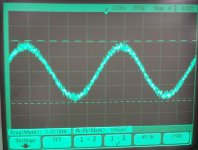
As an update, I did some testing in the lab today. My professor stopped by and taking a look at the circuit he said I would have to use a differential measurement instead of the direct one I had hooked up. It hadn't occurred to me that the - terminal of the amp isn't referenced to ground but -B. Once I hooked up two probes, and the RC filter I was able to see my input which was relieving. I do have two problems however, the waveform is still quite noisy looking; could this be inherent to the set up I have used being subject to noise? I can't imagine the real output is this noisy.
My other issue is that while I am using the math function of my o-scope to find the differential output of the amp, it doesn't allow me to do fft of the waveform, but only a single channel. I am thinking of capturing the waveform and analyzing it using MATLAB to find THD, but it would be nice if I knew some better method. Any suggestions?
I've attached the output that I did get to show the noise I am seeing. The input was 20mVP-P 1kHz. With a gain of 36, 20mV->720mV.
Attachments
Hi,
Are you able to do math operations to FFT results? You could do FFT on both channels and then subtract in the frequency domain. The result should be the same as subtracting in the time domain, i.e. FFT is a linear operator.
Really the best method would be using a good quality sound card / interface. They will have superior noise performance to even very expensive scope, but are, of course, limited in bandwidth. However, we are now mostly interested in audio range performance so it would be okay.
With a sound card you may or may not need to use any extra filtering as they will have some of their own and oversampling converters. However, be mindful of signal levels and maybe build a resistive attenuation pad to bring the signal levels down line level (1-2V max).
- Status
- Not open for further replies.
- Home
- Amplifiers
- Class D
- Class D IRAUDAMP7S clone o-scope measurement and issues