Active regulation is a pain. It introduces so many more parts and not just passive ones. So there are more things to go wrong. So unless in actually improves the sound it’s probably not worth it. Mark Levinson is a fan of active regulation, as you can see form there boards.
If we do want more backend regulation, other options are:
1)
Making the second C in the CRC network that exists now bigger. This CRC network was always an interesting thing to me. When the amp comes online the 10ohm resistors sees a short until the cap has some charge. For that brief moment in time the 10ohm resistor could have as much as 6A across it. That’s 360watts from a half watt resistor. I realize that the time of this serge is very short, but still this is well over the short term overload. This is why I’m afraid the raze this cap form 100uF to 1,000 or 2,000uF. I would like to understand how to calculate rated wattage for the resistor in DC RC networks. Also I see that Jens has moved the RC network back leaving one more stage unprotected, I don’t know what the logic was behind this.
2)
We could move up to a CLC filter AKA pi filter. I have seen some post where people have said that this makes thing sound worst, so maybe this is not a good idea. I’ll let others decide.
3)
One could use a separate small transformer to drive the back end. This is most likely the best way.
4)
Bryston uses a similar CRC as the leach but with a zener diode to ground. This keeps the voltage constant, however there is a 30V voltage drop across the regulator.
There are more ways of doing regulation all Jens has the do is not connect the back and the front end, just leave a jumper incase people don’t want the regulation. Does anyone have a comment on any of these forms of regulation, or any that I have not stated? All but number 4 are passive regulation.
In 1983, I took my Leach Monoblocks (Lower Power version) and compared them to another Leach amp that was built dual mono with large toroids >500VA per channel and with similar quality parts.
My regulated amp only sported 300VA hammond standard core with a couple of radio shack 12V@6amp booster transformers.
There was simply no comparison. The unregulated amplifier sounded positively undynamic in comparison. It was very apparent in kickdrums and really low bass transients. In the highs, the regulated amp seem to have more clarity. Yes, we checked the stability of both amps with scopes etc.
To prove that the power supply was the core of the differences, we disconnected his power supply and jumpered my regulator outputs to his amplifier boards. Now his amps sounded similar to mine.
Within a week, owner quickly retrofitted a front end only regulation using lifted discrete regulators ( I think 317/337) and while it had improved a bit, the fully regulated amp was still clearly superior. Needless to say, he had another project that converted his amp to full regulation.
A similar comparison was made with the super leach with similar results. Yes, on paper full regulation of the ouput appears to be unnecessary but close listening proves otherwise. PSRR etc. will say otherwise but the differences exist. Is it worth the extra effort and resources? It depends on what you desire. If you want that extra "kick" for dynamics. Higher wattage may NOT necessarily give that to you. Maybe the lower power version fully regulated might be better from a resource/parts standpoint.
Yes, regulation is very much more complex and requires a supply that can pass very high current transients but remember that a "super" amp is being contemplated.
Here's what might be interesting. In 1983, the regulator used was the one that was designed by James Boak in Amateur Audio. The core of this design was a current split arrangement with a three terminal LM-340T. ( Eeegads..... that's correct- the LM340T) . More modern 3 terminal devices likely will improve that design but the point is that even with such "old" devices there were easily audible improvements to be had over a simple power supply.
More recently ( loosely termed) about four years ago I decided to update some equipment I had built earlier. Where I had Sulzers, I put in Jung Super regulators, and the Sulzers displaced 3 terminal supplies.
Again each improvement in PS led to superior audio quality that was not too subtle at all.
I can only imagine what a good power amp with an up to date fast regulator would sound like!!!!!!!!
Who's up to that challenge?
Just a reminder:
normal regulation for a 1000 VA toroid is about 5 %
Put 120 vac on a 55 volt transformer for 110 vac and secondary voltage will be 60 volts.
With zero load voltage will increase with the 5 % : 63 volts.
I believe the measured voltage on the toroid transformer Terry bought at Ebay with zero load was a bit over 63 volts.
For the high voltage:
With the regulation of Terry's transformer a 125 V cap or higher would be needed, but a small one is enough, say 1000uF.
150 volt caps are expensive, 75 volt caps not.
Two 1000uF capacitors placed in series are equal to one 150 v cap.
In series the internal resistance of 2 caps in series is doubled.
As Bob Ellis mentioned, the current the regulator needs to deliver is not that high, esr for the regulator caps is not that important.
The regulator on Mr Thagard's A75 is a nice one, adapting it to the voltage used is easy.
I have been a huge fan of Mark Levinson builds, every ML amplifier is a piece of art.
A good example of ML regulation is the model 23, or 23.5
The 23 uses extensive regulation for the front end of the amplifier, a transformer with multiple voltage secondaries and separate powersupplies.
Pictures of it are plenty around on the web, at the French ML club, i can scan pictures of the model 23 brochure and post if you like.
Front end voltage does not need much more voltage than the output stage for continuous output with BJT's, voltage level is 1.41 times dc level anyway.
Transistors have a linear behavior within a range, a device often operates in class A, only a part of the current through the device can be used for voltage swing to avoid getting in the non-linear area.
And then it may be better to have a little slack on the voltage swing.
Front ends may have current stages to collect enough current for the next gain stage.
A current stage lowers max voltage swing.
On a Pass single ended amplifier thread NP mentioned a few weeks ago that he prefers to have some 5 volts headroom because that improves the sound quality of the design.
If there is sufficient voltage from the power supply, as Terry has on his transformer, putting some more voltage on the front end is not a bad thing.
Many of the designs with separate voltages for front and output stages, that i have seen, have a much higher voltage difference than just a few volts.
Designs that have voltage regulations for the front stage often have voltage levels considerably higher too.
A diesel engine operates on 90 % max continuous rating.
It can be used on 100 % constantly, usual is to keep 10 % slack.
As Mr Ellis said, regulators need heatsinks.
An easy regulator can be built with a lifted LM317/337 by raising the reference voltage on the regulator pin.
This can be done because the current the regulator will deliver is much lower than the maximum the LM's can handle.
Higher voltage drop induce higher dissipation, proper heatsinks are very important.
Usually an amplifer chassis has ample room for placing a few small regulator boards with heatsinks.
Discrete regulators are much better, i do not disagree with that.
I am a firm believer in stable power supplies.
The regulated power supply in figure 7 of the following Nelson Pass article is easily modifiable for this purpose by changing the zener diode values and the number of paralleled pass elements. The curcuit is simple and effective and has a low parts count. Why reinvent the wheel. Of course, because of the power required, a pretty good heat sink will be needed but that will be true of any linear power supply utilized with this amp. The other alternative is a SMPS which has other concearns.
Pass Active Supply Regulation
Pass Active Supply Regulation
Mikett,
I have never even considered total amp regulation. However, if it makes the huge improvement you claim, then it may well be worth it. Your claims do sound to be very conclusive. If it does not then I will be stuck with a transformer with higher rail voltage then I wish to use. Has anybody had similar observations? Could you post a schematic of your regulator and some pictures of your amp?
There aren’t to many schematics on line for total amp regulators, at these powers. I have found two possibilities. One is a circuit by Anthony Holton. He’s the one that built the really good sounding N-channel amp about a year ago, it was really popular. The only problem with it was it kept on exploding. It has good PSRR. However the circuit an only supply about 200 watts max, the schematic is almost unreadable, it’s not very well documented, and the parts are very difficult to pick up in the US. Here is a link:
http://www.aussieamplifiers.com/regulated.htm
The other option is a Pass regulator using mosfets for the power stage. It’s PSRR is not very good and the circuit has to be scaled up a little. But the circuit is so simple, that it is very easy to do. Right now it would be my preferred regulator. A schematic can be found at:
http://www.passdiy.com/projects/zenv3-6.htm
kilowattski said:The regulated power supply in figure 7 of the following Nelson Pass article is easily modifiable for this purpose by changing the zener diode values and the number of paralleled pass elements. The curcuit is simple and effective and has a low parts count. Why reinvent the wheel. Of course, because of the power required, a pretty good heat sink will be needed but that will be true of any linear power supply utilized with this amp. The other alternative is a SMPS which has other concearns.
Pass Active Supply Regulation
I've always thought that the power supply regulator of Mr. Pass is not suitable for this purpose.
If the current draw from the output of the regulator is not constant, the output voltage will also variate since the Vgs of the mosfet in the regulator will variate with the current through it.
For an amp that does not draw constant current from the PSU, I think what we need for regulating is a circuit with some feedback.
I can’t really comment on this as I don’t have the experience. However my guess would be that the zeners hold the Vgs constant, as long as the rail doesn’t drop to low.
There is a quote from Mr. Pass here that doesn’t sound to good:
There is a quote from Mr. Pass here that doesn’t sound to good:
The output impedance of this circuit is fairly low, being the inverse of the transconductance figure of the MOSFET, which for the IRFP240 is about 5 Siemens, which means that the output impedance will be about .2 ohms.
This figure is not particularly great as a regulator, and ordinarily we would look to improve on it, usually by enclosing the regulator transistor in a feedback loop to correct for this variation. If this were a higher power Class B or AB type amplifier, such an output impedance could easily result in one or two Volts of nonlinear distortion signal in the power supply, and this would bleed into the output circuit as distortion.
With a Class A amplifier, we have the advantage that the current draw from the supply is a linear function of the output current, and so no distorted "half waveform" is seen impressed on the supply voltage. This being the case, the importance of the output impedance becomes less, and we can consider using this follower without feedback.
My copies of the Boak supply is unfortunately deep in storage right now. However, the aritcles were written in the early 80s in the Audio Amateur. There were a series of articles called "Measuring Power Supply output impedance" or something along those lines. In these articles it was clearly shown that regulation actually reduces measurable distortion as well. The supplies that I used was the final version of the Boak where Walter Jung had recommended some changes that improved output impedance further. What we finally did was to incorporate two boards +,-, into one board that inclluded preregulators.
The heat dissipation and transistor was not a big issue. Why? If you choose a sufficiently "stiff" transformer to begin with, you can minimize the voltage on the pass transistors by running a lower unregulated voltage and minimize the heat produced. Furthermore, since there is also preregulator, the voltages that each of the pass transistors see might be only a few volts. With this you could probably get a modern TO3/multiple palstics that could pass maybe 50+ amps and still easily stay in the SOA. I used the MJ802/4502 and recall that I was good for 50 amps.
Unlike low level signal sections, a fast unstable supply in an amp of this power could have SUPER consequences. That's probably why not many have tackled this sort of thing much. The BOAK we used was proven to be stable over several power amps and that's why I was comfortable to scale it up and use it. But I'm sure it's performance might be laughable today, but you never know.
After this amp, I have not had the desire to build another amp for over twenty years because no significant ideas have come forward..
Mikett,
I think your circuit may be on display at: http://www.aussieamplifiers.com/regulated.htm
Anthony has added some improvements, can you confirm if this is the circuit you used.
Leve
I think your circuit may be on display at: http://www.aussieamplifiers.com/regulated.htm
Anthony has added some improvements, can you confirm if this is the circuit you used.
Leve
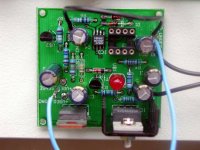
ALL-FET Dual low-noise regulator
2x+/-(24-40)V/200mA. Needs 2x(22-32)VAC
ONE 185.00 Euros
The EB-202/254 consists of two dual wide-band, low-noise regulators, using only FETs (JFETs and MOSFETs) as active elements. Maximum input voltage is ±45V and maximum output voltage is ±40V. Maximum output current with 5V input/output voltage difference is ±200mA.
The set-up procedure consists of adjusting the output voltage to the desired value. Connect 2x270 Ohm/5W resistors to the outputs and a DVM across one of the resistors. Connect the appropriate unregulated DC voltage to the regulator (should be approx. 5V higher than the expected output voltage) and check the output with the DVM. Adjust the output voltage to the desired value with trimpots P1/P2. If you have an oscilloscope and/or an audio µV meter, connect them across the load resistors and check the residual hum/noise. The scope should not show any ripple and the µV meter should show less then 5µV of noise over the audio bandwidth.
Attachments
acenovelty,
The Walt Jung Super-Regulator may have potential, the Borbely doesn’t it’s basically the same as the Anthony Holton circuit, but with fets and no component values. The maximum output voltage on the Borbely is way to low, and it’s allot of money to pay. You’re pay more for the intellectual property then you are for the board.
At this point the Anthony Holton circuit seems to be the best candidate. As the Pass would need feedback added or many more devices to compensate for the high resistance. The way I understand the problem is that when the amp draws instantaneous current from the regulator the voltage it outputs sags / modulates. To compensate for this the regulator with feedback senses the drop and sends even more voltage through.
Does anyone have more information on the Walt Jung Super-Regulator, the schematic does not talk about max input voltage or max output amps.
Another working circuit can be seen at LCAudio’s web site in the articles section. The only problem again is that the voltage is to low.
Leve
Maybe Al, the Mighty Mouse, made a proper suggestion, a separate thread for a voltage regulation circuit is more obvious.
I just asked for the possibility of separated lines on the Leach layout.
The first amplifier i heard (of) with full regulation was one by ML.
That amplifier was so stable that a German mag bridged the twins and welded a couple of bras strips together with them.
You could check at MarkLev.com for the regulation circuitry.
Or ask the ML expert here, Mr John Curl, maybe he can give some info on it. The ML20, 1st or 2st ed.
Andre Schmeets in Germany made a couple of designs with simple discrete voltage regulators.
One of his designs can easily be altered for +90 volts operation,
the original is around 80 Volts in.
From memory:
1 BD139/140 and 3 BC546/556, a couple of caps and R's
Attachments
- Status
- This old topic is closed. If you want to reopen this topic, contact a moderator using the "Report Post" button.
- Home
- Amplifiers
- Power Supplies
- Leach Super Amp Regulated supply