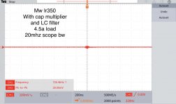
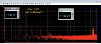
Last set of pics from me on this .. the cap multiplier suggested by Sangram does work well.
I reduced the filter to:8uH, cap multiplier, 20uf MLCC, 20,0000uF.
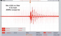
Some wanted scope shots so I added those as well. These are all at 4.5A loads.
Now back to work on the main amplifier 😀

I reduced the filter to:8uH, cap multiplier, 20uf MLCC, 20,0000uF.
Some wanted scope shots so I added those as well. These are all at 4.5A loads.
Now back to work on the main amplifier 😀
Attachments
Last set of pics from me on this .. the cap multiplier suggested by Sangram does work well.
I reduced the filter to: 8uH, cap multiplier, 20uf MLCC, 20,0000uF.
Some wanted scope shots so I added those as well. These are all at 4.5A loads.
Now back to work on the main amplifier 😀
Hi thanks a lot for the very interesting plots. This last is quite perfect. I wonder why the 50Hz peak ... and its harmonics ? from what i understand most of a smps noise should be related to its switching freq and so be a high frequency noise. I do not understand why that 50Hz 🙄
even if very low in level it ruins the floor/carpet ...
Thank you very much indeed. Smps are very handy also for some chip amps requiring 24-48 VDC. I am using one MW mod. DRP-240-24 on my desk (under the amp in the pic) .Hi ginetto- thanks for the kind words but I just measured the effects of what I think is just a basic simple passive filter anyone might use. ... Mlcc: multilayer ceramic capacitor.. say something like this: Blocked
i will try soon a 20A unit ...
Attachments
Last edited:
I wonder why the 50Hz peak ... and its harmonics ? ...
That's mostly environmental - later once everything is built into a case and shielded, these should mostly dissappear... 😀
Last set of pics from me on this .. the cap multiplier suggested by Sangram does work well.
I reduced the filter to:8uH, cap multiplier, 20uf MLCC, 20,0000uF.
Some wanted scope shots so I added those as well. These are all at 4.5A loads.
Now back to work on the main amplifier 😀
Hi, could you perhaps post a schematic of such a filter. This would help a lot. Also which kind of inductor do you use ? Thank you for this test, very interesting, i have a spare meanwell here, that i could use.
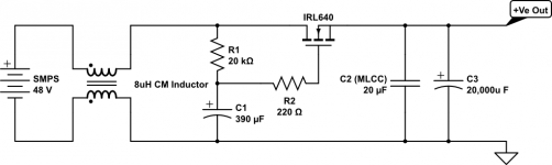
Schematic .... if I even can call it that !
Here is what I used - a super basic mosfet cap multiplier along with a few passives...
Logic level, high gm mosfet gave me better results compared to the old stalwarts like IRF240 etc.
Just search for parts starting with IRLxxxx and you’ll find lots to choose from (mostly to-220 cases for th parts).
All other parts values are non-critical. The only other component I think is important is the mlcc cap at the output. Expensive (2x10uf at $3.60each!) but effective!
I also swept the complete filter across a 50Mhz spectrum analyser to look for any weird peaks or resonances but found none. Just boring meh... 😀
Also see the fabulous filter in post 24 by pdfc9 for more (&better!) ideas !
Attachments
Last edited:
Hi ! thanks againThat's mostly environmental - later once everything is built into a case and shielded, these should mostly dissappear... 😀
 anyway that noise level is more than acceptable 🙂
Here is what I used - a super basic mosfet cap multiplier along with a few passives...
Logic level, high gm mosfet gave me better results compared to the old stalwarts like IRF240 etc.
Just search for parts starting with IRLxxxx and you’ll find lots to choose from (mostly to-220 cases for th parts).
All other parts values are non-critical. The only other component I think is important is the mlcc cap at the output. Expensive (2x10uf at $3.60each!) but effective!
I also swept the complete filter across a 50Mhz spectrum analyser to look for any weird peaks or resonances but found none. Just boring meh... 😀
Also see the fabulous filter in post 24 by pdfc9 for more (&better!) ideas !
Thank you very much. I need this also for a 5V stabilization and have only 5.5V input. How much will the loss be ? Is 5.5V enough to get at least 5V out ?
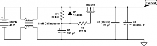
Milli not micro!
Thanks to an eagle eyed correspondent who pointed out the common mode choke value error ... it should be 8 millihenries (mH) and not uH!
😱
Also added the missing protection diode.
cheers!
Here is what I used - a super basic mosfet cap multiplier along with a few passives...
Thanks to an eagle eyed correspondent who pointed out the common mode choke value error ... it should be 8 millihenries (mH) and not uH!
😱
Also added the missing protection diode.
cheers!
Attachments
Thank you very much. I need this also for a 5V stabilization and have only 5.5V input. How much will the loss be ? Is 5.5V enough to get at least 5V out ?
Even with the logic level mosfets, the drop I measured was 2.3V. For your 5V application, I think just using the passive should be more than good enough !
Cheers !
Even with the logic level mosfets, the drop I measured was 2.3V. For your 5V application, I think just using the passive should be more than good enough !
Cheers !
Just using the passive is only the cm choke ? Or also a cap ? I need about 4A at 5V.
CM choke, electrolytic cap and the mlcc is what i'd use....
Thank you for advice. Will try it.
Thanks to an eagle eyed correspondent who pointed out the common mode choke value error ... it should be 8 millihenries (mH) and not uH!
😱
Also added the missing protection diode.
cheers!
Hi ! thank you very much for the kind and very valuable schematic.
I am sorry i am sure you have already explained why you have selected the mosfet instead of a bjt but could please direct me to the relevant post ?
i am very interested in cap multiplier ... but i understand there are some issues with mosfets ... and actualy i see normal bjts much more common, maybe in a darlington arrangement
Thanks a lot again, gino
Gino: Sorry I can help much. I just found mosfets much easier to deal with here.
There are many many good Cx multiplier designs to choose from, so i think you can compare easily.
I tried a BJT Cx multiplier with TIP142 using Rod Elliots designs but it appeared to (i think!) oscillate so I just surrendered without making much of an effort trying, as the only apparent benefit was lower volt drop...
I'll tell you this though: For sure, its not the device, just user error.😀
I'm sure the bipolar experts can suggest something that works well for you if you like to compare !
Last edited:
Gino: Sorry I can help much. I just found mosfets much easier to deal with here.
There are many many good Cx multiplier designs to choose from, so i think you can compare easily.
I tried a BJT Cx multiplier with TIP142 using Rod Elliots designs but it appeared to (i think!) oscillate so I just surrendered without making much of an effort trying, as the only apparent benefit was lower volt drop...
I'll tell you this though: For sure, its not the device, just user error.😀
I'm sure the bipolar experts can suggest something that works well for you if you like to compare !
Hi thanks a lot again, I was actually thinking to the same project with the TIP142 😉
My next step will be some sims ... just starting
Anyway the scope does not lie. Great design and congratulations again.
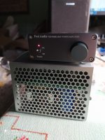
Thank you very much indeed. Smps are very handy also for some chip amps requiring 24-48 VDC. I am using one MW mod. DRP-240-24 on my desk (under the amp in the pic) .
i will try soon a 20A unit ...
I'm considering for a DC filament supply for a number of 6SN7s (600mA 6.3V) and 6AS7s (2.5A 6.3V). A 6.3V V+ & V- supply would work as the push pull has a B- line too so keeping the heater-cathode difference down would be useful so with running a linear for the HT so I'll need to tie them together (and I know some SMPS don't like this).
Oddly I have a Meanwell 12V B+/B- in my Koi pond drum filter controller - only having to return it for warrantee due to a water short 😱
- Home
- Amplifiers
- Power Supplies
- Mean well vs generic power adapter vs audio oriented smps