Yes, but those have quite a bit more noise and you have issues because there are now two noise sources in series. Depending on your DAC's current requirements, a simple TL431-based series regulator will be much better. Or an LM317, which is a much simpler circuit - at the expense of a bit of performance (almost negligible).
Yes, LM317 for the DAC maks sense due to the low power requirements. But, can I still use the buck converter for other 5V applications like USB hub, chargers, etc? Basically, my question was regarding series connecting anything with input capacitors (like the buck converter) to the Meanwell smps.
Thanks.
Thanks.
Yes, using a buck converter for non-audio applications is absolutely fine. Input caps aren't a problem as long as they're not diyAudio spec - which means below about 470uF. No buck converter I know has larger.
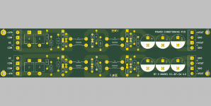
CMC power supply filter board
I am working on an audio amp and I designed a PCB for it because I originally planned on using two LRS-350-48 Meanwell supplies for it.
PowerAmpAudio/PowerCond at master * profdc9/PowerAmpAudio * GitHub
However, to use it, a metal chassis should be use so that the RF from the switching noise and other noise sources is separated from the supply rails.
Attachments
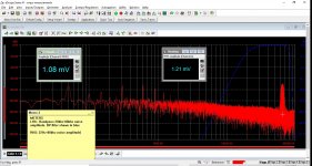
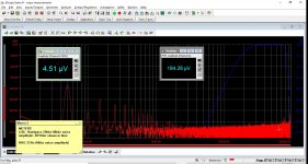
I did some measurements today for a Meanwell LRS350-48... loaded at 1A
- with L only - 8uH common mode inductor, and
- then L+C with 33kuF of capacitance (just to be absurd).
22hz-80khz bandwidth (and then in brackets Hi freq noise 20k-80k)
SMPS w/o filtering: 1.2mV (1.08mV)
L only filter : 457uV (62uV) ; wow that cm inductor really works !!
LC filter: 226 uV (11uV)
as above but with mains switch off: 184uV (4.5uV)
So not bad - adding some simple passive filtering makes these large & economical PSUs quite useful indeed.
ps the large cap triggers hiccup mode so beware ...
Attachments


Last edited:
At how much dbV does it get audible? Or thre isent a general rule? There is a large spike at 80khz how so? Do the transistors switch at such high speeds? You brought that curve down nicely, but should we even care about what happens after 20k? most speakers cant even reproduce those frequencies let alone the fact that class d output filters should turn them down, moreover who can hear after 20khz
The switching frequency is 160kHz, looks like. The spike at 80 would be the half-cycle switching spike.
I'm concerned about the load being too low to properly test ripple. I could expect the ripple to hit about 30mV at 50-60% load, which while high would still be acceptable and that is when you see the greatest contribution of LC filtering post the supply.
While the 50Hz spike looks bad, even the worst designs will have about 40dB of ripple rejection at low frequencies and this is not a problem. Would be very happy to see some results at higher load, as Meanwell's own datasheets show much higher ripple measurements when fully loaded.
At how much dbV does it get audible? Or thre isent a general rule? There is a large spike at 80khz how so? Do the transistors switch at such high speeds? You brought that curve down nicely, but should we even care about what happens after 20k? most speakers can't even reproduce those frequencies let alone the fact that class d output filters should turn them down, moreover who can hear after 20khz
True - nothing much beyond 20khz will eventually get amplified (or even reproduced !) Much of the ripple and noise is actually at lower frequencies tho so it makes the effort worthwhile...
The switching frequency is 160kHz, looks like. The spike at 80 would be the half-cycle switching spike.
I'm concerned about the load being too low to properly test ripple. I could expect the ripple to hit about 30mV at 50-60% load, which while high would still be acceptable and that is when you see the greatest contribution of LC filtering post the supply.
While the 50Hz spike looks bad, even the worst designs will have about 40dB of ripple rejection at low frequencies and this is not a problem. Would be very happy to see some results at higher load, as Meanwell's own datasheets show much higher ripple measurements when fully loaded.
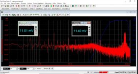
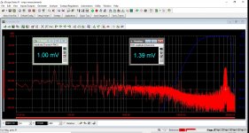
Here is the spectrum with a 4.5A load and as you pointed out - seeing more ripple. A second stage LC or a cap multiplier would clean this up nicely if required 😀
My two cents: I tried a Connex unit (SMPS800RE) some time ago. I used it to feed two ljm l25d units to drive a subwoofer. It worked flawlessly. I tried that amp to drive 2 way loudspeakers too and it was dead silent to my ears.
Gaetano.
Gaetano.
I’ve got a Douk Audio 400w 48v dc smps, a cheap smps from eBay. Would it benefit from replacing the no name caps with decent ones with the same rating? I have a 450v 100uf Nichicon that is about half the diameter of the one on the smps and I am not sure why.
@ElliJ the main benefit would be reliability. I doubt very much if it would improve the performance in any meaningful way.
48v Meanwell with 2 stage LC filter
After a lovely weekend with the fam, I spent a few hours in the shop this evening playing with this.
I added another L stage and MLCC cap at the output and compared the ripple and noise results against a few other usual suspects.
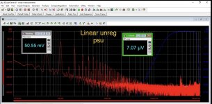
Here are the results when loaded at 4.5A (48v)
1. Linear unreg psu 20,000uf+0.47R+20,000uf: 50mV
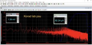
2. Korad lab psu: 1.4mV
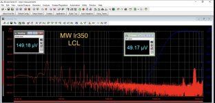
3. Mw lr350-48: 8uH+20,0000uF+8uH+20uf MLCC: 150uV
Pictures attached 😀 .. This gives good performance for a simple high current/voltage supply I think.
Sounds good enough but there’s a downside though... the otherwise good load regulation of the mw amps deteriorates because of the resistive losses in the inductors..😱
Next week I’ll try a cap multiplier instead of (one of?) the inductors to see how well it works....
After a lovely weekend with the fam, I spent a few hours in the shop this evening playing with this.
I added another L stage and MLCC cap at the output and compared the ripple and noise results against a few other usual suspects.
Here are the results when loaded at 4.5A (48v)
1. Linear unreg psu 20,000uf+0.47R+20,000uf: 50mV
2. Korad lab psu: 1.4mV
3. Mw lr350-48: 8uH+20,0000uF+8uH+20uf MLCC: 150uV
Pictures attached 😀 .. This gives good performance for a simple high current/voltage supply I think.
Sounds good enough but there’s a downside though... the otherwise good load regulation of the mw amps deteriorates because of the resistive losses in the inductors..😱
Next week I’ll try a cap multiplier instead of (one of?) the inductors to see how well it works....
Attachments
Last edited:
Hi ! do you have the plot of the Mw lr350-48 alone maybe ?
thanks a lot
Sure... from a few posts earlier, here is the Lr350-48 alone with no filtering. The load is 4.5A.
Attachments

Sure... from a few posts earlier, here is the Lr350-48 alone with no filtering. The load is 4.5A.
Hi thank you very much indeed for the very kind and valuable reply.
I am very impressed about the psrr of the passive filter you designed.
You have said above
sorry ... what is a MLCC cap ?...I added another L stage and MLCC cap at the output ...
Then i wonder if passive filters can be simulated with some SW ... just to play with different values and see the optimum ones.
And if they are equally beneficial with lower current draws.
Did you listen to the filtered smsp ? any improvements in the sound ?
thanks a lot again
Hi ginetto- thanks for the kind words but I just measured the effects of what I think is just a basic simple passive filter anyone might use.
The meanwell had been suggested by others and Nelson pass too so I thought I’d try it and have really liked them better than my linear unreg psu. Even amps with high measured psrr benefit from lower psu ripple. When psrr is measured, the amplifier input is shorted. In a good symmetrical amplifier, the psrr measured like this is high and the psu ripple is cancelled out.
However in real life, there is signal present at the same time, creating intermodulation products with the psu ripple. This doesn’t get cancelled out by symmetry (but will be reduced a lot by feedback error correction of course) . This this a known effect can be measured easily...and may explain (in part) why some people prefer smps supplies for their amps. I just googled and found this: https://www.tij.co.jp/jp/lit/an/slea049/slea049.pdf
Of course there are so many high end smps to choose from, but my interest was seeing how to tweak this model in particular.
Mlcc: multilayer ceramic capacitor.. say something like this: Blocked
Last edited:
- Home
- Amplifiers
- Power Supplies
- Mean well vs generic power adapter vs audio oriented smps