I was thinking of purchasing this, in order to use for a tube preamp. It puts out 380V @ .65A.
1/2/4Pcs 7R 230W 5R 200W Moving Beam Head Light Ballast Power Supply Disco | | eBay
There are quite a few others, perhaps with better pictures. Just type in "Moving Beam Power Supply" into ebay.
There's even a few videos on youtube. This one a guy is troubleshooting it:
YouTube
What are your educated guesses as to whether that 380V is isolated? Can you tell by looking at it?
If isolated, I'll probably buy it, and post some measurements and tests in this thread.
It does have a power transformer with the right voltages on the label.
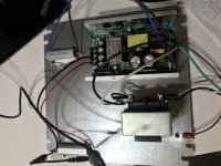
I see that. But the label looks like it's for the whole unit. The 380V output is right next to the mains input, which is the thing giving me pause.
But there are 2 transformers. I'm thinking one is for the 380V, and the other is for the 12/24V.
But the label looks like it's for the whole unit. The 380V output is right next to the mains input,
which is the thing giving me pause.
Probably you can't count on having isolation.
Last edited:
Some initial results
So, I bought one of these and here are some results:
I'm not entirely sure if this unit is isolated, so I hooked it up to an isolation transformer that I bought for $15.
I loaded the HV with a 10k resistor and also tested the 24V output through a 15R resistor.
On startup the unit makes 3 quick "tick tick tick" sounds. At each tick, the voltage climbs.
See the video: the very bottom of the scope is at 0V and the top is 400. It jumps to 200, then 300 and then finally almost 400. I'm not really sure what that's about:
iCloud
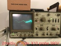
I measured the HV at 392V. See the attached pic, showing the AC component at 120 Hz. Ripple was much smaller than I expected at only around 1V or so.
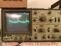
On the 24V side, the AC component was a little spikier looking, but frequency was at 50kHz. Ripple was about 1V p to p.
Thoughts?
So, I bought one of these and here are some results:
I'm not entirely sure if this unit is isolated, so I hooked it up to an isolation transformer that I bought for $15.
I loaded the HV with a 10k resistor and also tested the 24V output through a 15R resistor.
On startup the unit makes 3 quick "tick tick tick" sounds. At each tick, the voltage climbs.
See the video: the very bottom of the scope is at 0V and the top is 400. It jumps to 200, then 300 and then finally almost 400. I'm not really sure what that's about:
iCloud
I measured the HV at 392V. See the attached pic, showing the AC component at 120 Hz. Ripple was much smaller than I expected at only around 1V or so.
On the 24V side, the AC component was a little spikier looking, but frequency was at 50kHz. Ripple was about 1V p to p.
Thoughts?
Attachments
Last edited:
I'm not entirely sure if this unit is isolated,
You can check with an ohmmeter from the input to the output terminals. You should see opens on all if it's isolated.
I loaded the HV with a 10k resistor
That's only 16W, which is fine if that's all you need but they advertise 200W. That would require a roughly 800 ohm load for testing. You can get cheap 100W resistors on eBay, use a few in series or parallel, preferably mounted on a large heat sink. The ripple goes up very substantially with the load, so you want to test at a current/power level at least as large as the largest you are likely to use in the intended application.
25/50/100W 0.01-5k Ohm Watt Shell Power Aluminum Housed Case Wirewound Resistor | eBay
I measured the HV at 392V. See the attached pic, showing the AC component at 120 Hz.
Are you sure? That would suggest that the high voltage part is not a SMPS but just a transformer and rectifier. And that transformer looks way small for 200W at 60Hz. I expect if this is true, the output voltage will sag greatly at the rated power.
Ripple was much smaller than I expected at only around 1V or so.
You're testing at less than 10% of rated power so I would expect low ripple. See what happens at 200W.
On the 24V side, the AC component was a little spikier looking, but frequency was at 50kHz. Ripple was about 1V p to p.
At what ouput current?
Last edited:
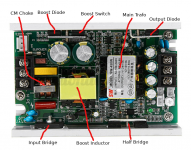
The label claims it has a power factor of 0.95 so it is extremely likely that it uses active power factor correction. That generally uses a boost convertor on the primary side to produce a 400V DC bus. You will get a bridge rectifier, a boost mosfet and a boost diode. Common mode choke and boost inductor. The rest looks like it is a half bridge with the main transformer and possibly resonant mode. Sorry... the 400/380V is not isolated.
Attachments
Very interesting. This is a ballast (PSU) for a moving light fixture. The gas arc lamps in these fixtures typical run at 24 volts DC. The 380V is used to strike the arc. It's just a few brief pops of HV then once the arc is struck the HV is not used again. It's only the igniter. That makes me think it would not be high current, at least not for long.
In a smart ballast the igniter circuit will pop a few times until it senses current flow thru the lamp. If the lamp failed to ignite, the ballast shuts down and sends an error message. Video projectors also use these type lamps and ballasts.
In a smart ballast the igniter circuit will pop a few times until it senses current flow thru the lamp. If the lamp failed to ignite, the ballast shuts down and sends an error message. Video projectors also use these type lamps and ballasts.
I'm actually considering using this for a tube preamplifier so I tested power roughly in the range that I will need. Def not comfortable using at 200W. I might do a test at double my requirements, but I don't want to do an exhaustive stress test to it's limits.
I'm definitely sure that the HV is at 120Hz. Just to make sure I had the range correctly set, I put the scope directly on my isolation transformer first, to make sure I had a reliable 60Hz reference.
I'm definitely sure that the HV is at 120Hz. Just to make sure I had the range correctly set, I put the scope directly on my isolation transformer first, to make sure I had a reliable 60Hz reference.
You can check with an ohmmeter from the input to the output terminals. You should see opens on all if it's isolated.
That's only 16W, which is fine if that's all you need but they advertise 200W. That would require a roughly 800 ohm load for testing. You can get cheap 100W resistors on eBay, use a few in series or parallel, preferably mounted on a large heat sink. The ripple goes up very substantially with the load, so you want to test at a current/power level at least as large as the largest you are likely to use in the intended application.
25/50/100W 0.01-5k Ohm Watt Shell Power Aluminum Housed Case Wirewound Resistor | eBay
Are you sure? That would suggest that the high voltage part is not a SMPS but just a transformer and rectifier. And that transformer looks way small for 200W at 60Hz. I expect if this is true, the output voltage will sag greatly at the rated power.
You're testing at less than 10% of rated power so I would expect low ripple. See what happens at 200W.
At what ouput current?
Are you saying that the HV cannot run continuously at all, or just not at high current? I was considering using it for a salas 6v6 preamp, which only requires ~20ma X 2 tubes + I might use a maida regulator after it, so lets say 60ma max.
To use this PSU as it was intended with a DJ light, it actually requires another part, which is the ballast itself.
See: 7R 230W Moving Beam Light Ballast Driver Stage Light | eBay
Here's an interesting link of a guy repairing a DJ light, and installing the PSU:
YouTube
To use this PSU as it was intended with a DJ light, it actually requires another part, which is the ballast itself.
See: 7R 230W Moving Beam Light Ballast Driver Stage Light | eBay
Here's an interesting link of a guy repairing a DJ light, and installing the PSU:
YouTube
Very interesting. This is a ballast (PSU) for a moving light fixture. The gas arc lamps in these fixtures typical run at 24 volts DC. The 380V is used to strike the arc. It's just a few brief pops of HV then once the arc is struck the HV is not used again. It's only the igniter. That makes me think it would not be high current, at least not for long.
In a smart ballast the igniter circuit will pop a few times until it senses current flow thru the lamp. If the lamp failed to ignite, the ballast shuts down and sends an error message. Video projectors also use these type lamps and ballasts.
Hard to say, I've never had to put a PSU like this thru any kind of test, only replace it when it fails. Just relating what I know of lamp systems like this.
Definitely test it to see if it can supply the current you need for long periods. That will tell you for sure. I thought that the igniter circuits were higher voltage than 350V, but I could be wrong, or maybe it's stepped up further down stream. But I usually deal with larger lamps.
I suppose you could also use the 12 or 24V for heaters.")
Definitely test it to see if it can supply the current you need for long periods. That will tell you for sure. I thought that the igniter circuits were higher voltage than 350V, but I could be wrong, or maybe it's stepped up further down stream. But I usually deal with larger lamps.
I suppose you could also use the 12 or 24V for heaters.
Updates
As promised, ran some additional tests.
--
Previously, I had the HV through a 10K resistor.
V = 392V
I = 39mA
V ACp-p ripple was 1v
f = 120Hz
ran for just a few minutes
--
UPDATE, now through a 5k resistor
V = 392V
I = 78mA
V AC p-p ripple 2V
f = 120Hz
ran for 40m
Also tested the 24V side again. This time I decreased the load (30R vs 15R before), since my resistors didn't have enough sink for a longer test
Results were similar to before: 50kHz switching, around .4 V p-p ripple, but was a little less spikey- a bit cleaner. Also ran for 40m.
Now that I've got the rig all set up, I'll test for 4-5 hours next time.
All in all, seems pretty stable. I also checked for continuity between the HV 0V and earth, as well as HV 0V and N and L and there was none. Not sure if that means it's totally isolated or not. Still running it through the isolation transformer, and will continue to do so just to be safe
Last edited:

Very interesting. Appears to be well regulated. No sag with the increased load. If it can deliver the advertised 0.65A at 380V continuously, it would make a dandy supply for a good size power amp.
I am not a SMPS expert, so I'm baffled by the 120Hz ripple. I would expect it to be in the many kHz range, not line frequency.
Thanks for posting the results and good luck with the testing.
I am not a SMPS expert, so I'm baffled by the 120Hz ripple. I would expect it to be in the many kHz range, not line frequency.
Thanks for posting the results and good luck with the testing.
Someone mentioned previously that is probably because it utilizes a pfc module at the input.
I just googled "power factor correction output ripple" and this article popped up:
Output Line Ripple on Power Factor Corrected AC-DC Power Supply Outputs (Part 1) | Vicor PowerBlog
It says:
"As a result of that power factor correction, because we want to draw current proportional to the rectifier input voltage, the output DC bus voltage has ripple at twice the line frequency. Doubling of the line frequency occurs because of the input rectifier.
"
I took only one Power E course back in the day, so I don't fully understand it and can't explain it. Maybe someone can chime in, or maybe someone explained it elsewhere on this site- I'll look around.
- Status
- This old topic is closed. If you want to reopen this topic, contact a moderator using the "Report Post" button.
- Home
- Amplifiers
- Power Supplies
- 380V Moving Beam Power Supply - Ebay