7 volts in and only 0.5 volts out is pretty conclusive its duff.
When unloaded the unregulated input voltage will rise, perhaps quite a lot because small transformers have very poor regulation. The difference in transformer output voltage between full load current and no load current can be anywhere from 20% to 50% for really small transformers. That is what the 'regulation figure' given in transformer data sheet means. A big toroid might be in the 5% region.
When unloaded the unregulated input voltage will rise, perhaps quite a lot because small transformers have very poor regulation. The difference in transformer output voltage between full load current and no load current can be anywhere from 20% to 50% for really small transformers. That is what the 'regulation figure' given in transformer data sheet means. A big toroid might be in the 5% region.
Hi , i have the 3.3 reg fitted and have the 3.3 volts back and stable .. still no power up though , i don't seem to have the STBY_CNT , trying to understand the schematic i think it comes from the relay ? . with 240 across the relay pins 2 /3 i should get the same voltage on pins 1 and 4 , i have 8 vDc on pin 1 and 0.3 v on pin 4 .
Does this suggest the relay is bad ? . it does click when powered on

Does this suggest the relay is bad ? . it does click when powered on
Last edited:
Something weird must have happened to this player... we keep finding definite faults and replacing the parts we suspect does fix each problem we have found and yet still there are more issues. It reminds me of lightning damaged equipment which I have worked a lot on over the years.
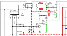
That bit of the circuit looks like this to me...
1/ If that red dotted supply is over 11 volts then the zener conducts and turns ON Q3904. That clamps the STBY CNT line to ground and means the relay is always held off.
2/ If the rail is below 11v then Q3904 is OFF and the relay driver Q3905 is able to be turned on via the CNT line. That line must go high. If we are on 3.3 volt logic then it should be at that value. Or it may be 5 volts. High anyway.
Is Q3904 some kind of over volt protection? Seems a bit odd, however...
You can always stick a screwdriver across Q3905 (really") ) and see what happens and if it powers up.
) and see what happens and if it powers up.
That bit of the circuit looks like this to me...
1/ If that red dotted supply is over 11 volts then the zener conducts and turns ON Q3904. That clamps the STBY CNT line to ground and means the relay is always held off.
2/ If the rail is below 11v then Q3904 is OFF and the relay driver Q3905 is able to be turned on via the CNT line. That line must go high. If we are on 3.3 volt logic then it should be at that value. Or it may be 5 volts. High anyway.
Is Q3904 some kind of over volt protection? Seems a bit odd, however...
You can always stick a screwdriver across Q3905 (really
) and see what happens and if it powers up.You should always have supply voltage on one side of the relay coil and which is the stripey end of the diode across the coil. If you short the transistor out then that supply voltage should then be across the coil and the relay should operate.
If the supply to the relay disappears when you short the transistor out then check the diode is OK and not shorted.
If the supply to the relay disappears when you short the transistor out then check the diode is OK and not shorted.

Ah. So it is clicking correctly when you short the transistor out. So we know the relay and supply are OK.
So with the relay on (transistor shorted) what is the logic level on the STBY-CNT line?
Does whatever voltage you see on that line vary as you operate the units front power button. Does the logic level change?
Is there any kind of display showing?
So with the relay on (transistor shorted) what is the logic level on the STBY-CNT line?
Does whatever voltage you see on that line vary as you operate the units front power button. Does the logic level change?
Is there any kind of display showing?
Do you mean the relay clicks on as soon as you apply power?
If so then that means transistor Q3905 has to be conducting and that in turn means the STBY CTRL line has to be high (so check that voltage level on that line)... or there is a problem around Q3905.
Nothing else can make that relay click on. So we need to know which of the two scenarios it is.
If so then that means transistor Q3905 has to be conducting and that in turn means the STBY CTRL line has to be high (so check that voltage level on that line)... or there is a problem around Q3905.
Nothing else can make that relay click on. So we need to know which of the two scenarios it is.
Do you mean the relay clicks on as soon as you apply power?
If so then that means transistor Q3905 has to be conducting and that in turn means the STBY CTRL line has to be high (so check that voltage level on that line)... or there is a problem around Q3905.
Nothing else can make that relay click on. So we need to know which of the two scenarios it is.
yes , relay clicks on and off with power .
If you have the resistor shorted then that alone would be enough to stop the relay pulling in. If you also have to desolder a pin on the transistor then the transistor is faulty. It means it is conducting when it should not.
Shorting the resistor 100% removes the base current needed to turn it on. You should see no voltage across the relay coil in that state.
And when the relay is on, does the player display light up etc or is it still all essentially dead?
Shorting the resistor 100% removes the base current needed to turn it on. You should see no voltage across the relay coil in that state.
And when the relay is on, does the player display light up etc or is it still all essentially dead?
when i connect the power board up to the rest of the player the relay does not click in , thats with the resistor still shorted .
No life from the display..
It sounds like there is more weird stuff going on here.
Maybe I'm not following you on this
This test result makes sense. The relay should never click in when the resistor is shorted:Then you say:
The relay still operates and still have 8v on pin 1 and .3 v on pin 4 of the relay with the resistor shorted
If you have 8 volts on one end of the relay coil and 0.3 on the other then the relay has clicked on, and which it should not do with the resistor shorted.
I'm just trying to be clear what is happening but it does sound like other stuff is faulty as well. Do you see
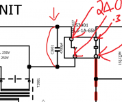
So we could move away from this area and try deliberately adding a link across C3931 which would permanently apply 230 volt mains to the main transformer no matter what else was going on. You could then see if that led to any clues such as rails derived from that larger transformer being missing.
Attachments
With R3914 shorted the relay must not click at all.
Look at the diagram. With the resistor shorted the transistor is permanently OFF. That means that NO voltage should appear across the relay coil.
In other words if you measure across the coil you must see zero volts.
This is also confirmed by you seeing the same voltage at each arrowed location. If you have 8 volts on one side of the coil then you must have 8 volts on the other. Both points must be the same voltage which equals NO difference between them.
If that is not so then the transistor must be faulty or your actual circuit is different from the one we are working to.
Shorting the cap out completely overrides that part of the circuit and so it doesn't matter what is shorted or not around the transistor.
Attachments
- Status
- This old topic is closed. If you want to reopen this topic, contact a moderator using the "Report Post" button.
- Home
- Amplifiers
- Power Supplies
- marantz cd6006 power supply issue