Pin 6 of your transformer appears to be desoldered from the board. Is that intentional?
We were seeing if the transformer voltage in isolation held up under a load and also to try and prove if the problem was tranny related or whether it was the circuitry hung off it.
Pin 6 of your transformer appears to be desoldered from the board. Is that intentional?
.
reconnected transformer getting 3.5 v this time , still 3.5 with those 2 diodes out .. back up to 9v with the 4 diodes out
So the circuitry supplied via the four diode bridge appears to be the culprit. I'll have a think...
The CD6005 looks very similar.
Things to check.
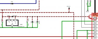
1/ Be 100% certain that all four diodes in the bridge are OK. One leaky one would pull the voltage down.
2/ Make sure the diode across the relay coil is OK. If it was shorted/leaky then it would pull the voltage down via transistor Q3905 which is the relay driver.
Now it gets more difficult...
Very important question. In post #1 you mention it works OK when you apply power to the big transformer. Did you mean the whole player works as normal? If that is so then continue...
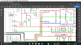
If you look at the diagram it shows that the rail from the standby transformer is over ridden via D3929. In other words when the main rails are up this diode conducts and takes over reducing load on the little transformer.
Is that diode OK and not leaky?
Check also C3929 and C3924.
If we get to this point then there may be doubts thrown on the little transformer once again. It all seems as if it just can not supply quite enough current, but lets take it one step at a time.
I mentioned a PP3 battery earlier. Using one would give a good clue as to the current draw of all this circuitry.
Things to check.
1/ Be 100% certain that all four diodes in the bridge are OK. One leaky one would pull the voltage down.
2/ Make sure the diode across the relay coil is OK. If it was shorted/leaky then it would pull the voltage down via transistor Q3905 which is the relay driver.
Now it gets more difficult...
Very important question. In post #1 you mention it works OK when you apply power to the big transformer. Did you mean the whole player works as normal? If that is so then continue...
If you look at the diagram it shows that the rail from the standby transformer is over ridden via D3929. In other words when the main rails are up this diode conducts and takes over reducing load on the little transformer.
Is that diode OK and not leaky?
Check also C3929 and C3924.
If we get to this point then there may be doubts thrown on the little transformer once again. It all seems as if it just can not supply quite enough current, but lets take it one step at a time.
I mentioned a PP3 battery earlier. Using one would give a good clue as to the current draw of all this circuitry.
Attachments

the 4 bridge diodes are good ,the relay diode there looks to be a diode and a zenner diode (D3934/D3935) but they both seem to test the same ? , when i said it works ok i meant the big transformer works ok , i didnt try to power the player on , i cant seem to find D3929 on my board .
the C3929 / C3924 , it is ok to have a lower esr than the charts say ? .
I have a bench psu (if better than a battery)

the C3929 / C3924 , it is ok to have a lower esr than the charts say ? .
I have a bench psu (if better than a battery)
Last edited:
Low ESR is fine and mostly considered better.
A bench PSU could be ideal as long as the current is limited. Perhaps add a 10 ohm in series with the plus lead and that way we can measure DC volt drop across it and calculate the current.
Maybe that diode is part of the difference between models.
A bench PSU could be ideal as long as the current is limited. Perhaps add a 10 ohm in series with the plus lead and that way we can measure DC volt drop across it and calculate the current.
Maybe that diode is part of the difference between models.
Also I think you could connect the PSU across the tracks pins 6 and 8 of the transformer connect to (having isolated a pin as before). The configuration of a bridge rectifier including those other two diodes means that it would not matter what the polarity was.
Doing that would power up all sections and the player should work normally if everything is OK.
Doing that would power up all sections and the player should work normally if everything is OK.
My PSU has current limiting , i found D3929 , it was buried under some white sealant , it tested ok . I now also have the service manual ..
So next i am injecting 9 volts from the psu into the line the small transformer powers ,
So next i am injecting 9 volts from the psu into the line the small transformer powers ,
Hmmm...
So if we assume the diagrams to be similar it looks like U3906 is an 'all time' 5 Volt supply.
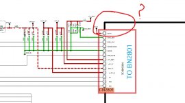
You now need to isolate pin 13 on the multiway plug (check yours is similar though) and see if the 5 volt rail come up... or not. If it does then we have to look at everything fed off that line, if it doesn't then the reg or one of its immediate components could be faulty.
Process of elimination I'm afraid.
So if we assume the diagrams to be similar it looks like U3906 is an 'all time' 5 Volt supply.
You now need to isolate pin 13 on the multiway plug (check yours is similar though) and see if the 5 volt rail come up... or not. If it does then we have to look at everything fed off that line, if it doesn't then the reg or one of its immediate components could be faulty.
Process of elimination I'm afraid.
Attachments

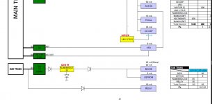
I'll have to leave this for today but the weird thing is that the circuit diagram doesn't seem to show where the 5 volt line goes...
The block diagram also seems to omit this 5 volt supply.
You might need to do a bit of physical tracing of where the line goes.
The block diagram also seems to omit this 5 volt supply.
You might need to do a bit of physical tracing of where the line goes.
Attachments
looks the same .
It does, but if you look at where it goes then it seems to vanish. Look at the block diagram as well.
Last post...
Isolate the reg as I suggested and see what that shows.
If the reg does feed anything then typical things could be the infra red remote receiver etc... one for tomorrow 🙂
Isolate the reg as I suggested and see what that shows.
If the reg does feed anything then typical things could be the infra red remote receiver etc... one for tomorrow 🙂
when you say isolate pin 13 , how would i do that ?
Same way as you did the transformer... I think you figured it out 🙂

- Home
- Amplifiers
- Power Supplies
- marantz cd6006 power supply issue