120dB rejection within a single block is feasible (which doesn't mean the sim can be relied upon at this kind of level).1) One thing I wonder, which was raised on another thread, is how low can considered realistic or feasible.
In that case I was playing with an LT3042 PSSR curve, which got very low.
The question that was raised was "-196dB is not creditable in a real-world circuit. It "might" happen through lucky cancellation. Or expect to real-life measure (or hear!) it.
>100dB is creditable, in a simulation, although real life parasitics will spoil this."
140dB would really be pushing it, but might still be feasible with lots of precautions (that's about what the nonoiser achieves).
160dB or similar figures are pies in the sky: you would need at least two drastically separated blocks to achieve that, and the wiring, both for the interconnect and the test connection would need great attention.
Excellent sim figures need to be confirmed in reality, because lots of very low-level effects and interactions are not taken into account.
Basically, anything better than -100dB needs a real-world confirmation. (and figures much worse than that can also be widely optimistic, but better than 100dB is automatically suspicious)
Last edited:
The real question, as always, is how much is very good and we should be satisfied with.
Instead of just running around with the donkey and the carrot.
What I could guess from your words is that something between 100-120dB rejection is a good figure, something to be content with and consider other factors. Like how difficult it is to build or how expensive it might be the parts.
All regulators, except the original from the Luxman pre, seem to equal or exceed the -100 to -120dB PSRR spec in the 10-20KHz audio range.
Would you agree with that?
So now comes the question of impedance and noise.
Very broadly probably, but the devil is in the details, in particular the physical implementation: placing one pad of a bypass cap 5mm towards the wrong side could completely ruin it, which is why a reality check is essentialWould you agree with that?
One thing that I would like to see implemented are the Denoiser and the Nonoise regulators you designed.
Until now only one person built a Denoiser and seemed to have some problems with the output capacitor, if I remember well. Using a ceramic 1uF cap instead of an E-cap, as you had recommended.
Would a Denoiser piggy back pcb be critical in any way, except for the resistor that should not be used with the LM337?
Also no one has yet built a Nonoise, both in positive and negative versions, particularly taking care of the Kelvin connectors.
For my particular application, if I choose to go either with the Sulzer or Jung regulator I will have to go for the simpler version, as to go from 35v at the pre-regulator input and end up in 30v output things would have to be critical from the raw supply and the wall line stability.
But for the lower voltage regulators using a "full" Jung regulator would be fine.
In any case, the simulations I am doing for the Sulzer and Jung regulators do not use pre-regulator.
It would be fine to design the pcbs, following your suggestions, for the Denoiser and NoNoise regulators, and take the chance to listen to them and compare with the preamps themselves.
Until now only one person built a Denoiser and seemed to have some problems with the output capacitor, if I remember well. Using a ceramic 1uF cap instead of an E-cap, as you had recommended.
Two , at least , Khadgar2007 and his friends on another forum build DeNoisers too.
For me it was ceramic 1uF or 100nF WITH (and without) 100uF or more. LM317 was not a problem , just wanted a larger input cap. Only the LM337 absolutely rejected the ceramics.
I build 2 of each , but I can't test them for noise . Just listening with a HP , I couldn't hear anything after a LM317 + Cadj , but that could be my older ears.
As I tested before , white noise at -95 dB was inaudible ... to me.
Another question for Elvee :
If a ceramic cap is behind a diode , will it make the LM337 + DN unstable again ?
I ask this because the voltage fault detectors right at the DN's output will have them.
On another thread I opened, specific for the LT3042 regulator, I have been getting absolutely remarkable results in PSRR and particularly impedance.
https://www.diyaudio.com/forums/pow...mulation-2.html?posted=1&posted=1#post5999075
Fortunately voltages are somewhat limited, as maximum input is 20 volts. So I wouldn't be able to use it on the Luxman preamp.
The other thing is that the LT3042 is designed to be assembled with SMD parts, which I must confess I'm not too good with. Also designing the pcb is trickier and more restricted on what you can do. OTOS things are quite small, so the whole regulator also ends up being small.
There are several ready made basic LT3042 pcbs on eBay that perhaps could be used, adding some extra parts.
As on the other regulators, adding a CRC filter at the input worked marvelously to improve the PSRR curves.
Two , at least , Khadgar2007 and his friends on another forum build DeNoisers too.
For me it was ceramic 1uF or 100nF WITH (and without) 100uF or more. LM317 was not a problem , just wanted a larger input cap. Only the LM337 absolutely rejected the ceramics.
I build 2 of each , but I can't test them for noise . Just listening with a HP , I couldn't hear anything after a LM317 + Cadj , but that could be my older ears.
As I tested before , white noise at -95 dB was inaudible ... to me.
Another question for Elvee :
If a ceramic cap is behind a diode , will it make the LM337 + DN unstable again ?
I ask this because the voltage fault detectors right at the DN's output will have them.
Eliminating the resistor on the LM337 regulator, as Elvee suggested, didn't solve the unstability problems you had with the negative Denoiser?
Why did you insist on using the 1uF ceramic cap at the output, instead of the E-cap that Elvee did suggest?
Eliminating the resistor on the LM337 regulator, as Elvee suggested, didn't solve the unstability problems you had with the negative Denoiser?
Why did you insist on using the 1uF ceramic cap at the output, instead of the E-cap that Elvee did suggest?
I haven't tried putting back the 1uF/100nF after taking out the 33 ohm. The DN's are now soldered to the Mosfet switches , which has to be switched in a 2 step sequence to gradually load the 6700uF caps behind it and that has to be done by the start/protection circuit that I haven't build yet. I'm not going to risk those switches doing it by hand.
My DN test circuit is only for the LM317 , not 337.
Like I said before : after seeing Elektor putting ceramics with E cap's at the output of LM and 78xx regulators for decades , I did the same , I didn't think the DN could get upset by a mere 1uF or even 100nF.
I only tested the 337 very recently, and it looks a bit more difficult than the 317; it certainly behaves (slightly) differently, and that is true for unmodified regulators too: the 337 is known to be less docile.LM317 was not a problem , just wanted a larger input cap. Only the LM337 absolutely rejected the ceramics.
You can do a very simple test: connect a phono preamp to the supply (via a 100n blocking cap and a 1K anti-surge resistor, of course) and listen to the resultI build 2 of each , but I can't test them for noise . Just listening with a HP , I couldn't hear anything after a LM317 + Cadj , but that could be my older ears.
As I tested before , white noise at -95 dB was inaudible ... to me.
No: this kind of resonance is completely local, and will be destroyed by any kind of series damping.Another question for Elvee :
If a ceramic cap is behind a diode , will it make the LM337 + DN unstable again ?
A run of several centimeters of wiring would probably be sufficient too: the resonance will still exist, and might even be stronger, but it will be pushed lower in frequency where it can be handled properly.
Note that in my breadboard test, the 337 became stable with a 10µF, even if it was ceramic.
Combinations are more hazardous and less predictable, because there are many more parameters coming into play
Elektor is what it is, but paralleling capacitors can sometimes make sense: one E-cap directly at the output of the regulator, and a ceramic bypassing the point of load: logic circuit, opamp, etc.Like I said before : after seeing Elektor putting ceramics with E cap's at the output of LM and 78xx regulators for decades , I did the same , I didn't think the DN could get upset by a mere 1uF or even 100nF.
Sometimes, adding a small series damping resistor (1 ohm f.e.) can help a lot.
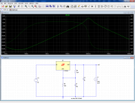
As a picture is worth a thousand words, here is an example of how a regular 317 behaves with just a good ceramic at its output.
The graph shows the output impedance with a static load of 20mA:
You can see an obvious peak at ~100kHz. Not too nasty, but the reality is somewhat harsher.
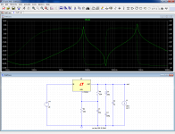
Now, use something like your combination (an inductance of 50nH is realistic for the tracks+internal cap inductance):
You see immediately that the situation has been degraded and complexified, with 3 resonances.
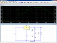
With just a 0.47 ohm damping added somewhere, things become much more relaxed (note the vertical scale):
You could think that all this is simulation and is not reflected in reality, but somewhere on this forum I have posted real VNA screenshots showing exactly the same thing.
Attachments
You can do a very simple test: connect a phono preamp to the supply (via a 100n blocking cap and a 1K anti-surge resistor, of course) and listen to the result
Sorry, I am in 2019 ... who still uses a phono preamp , except for carlmart ?
")
And sorry for asking the DeNoiser question here on the RIAA thread. Carlmart's link at the DeNoiser, https://www.diyaudio.com/forums/pow...celler-retrofit-upgrade-317-based-reg-35.html made me click on it expecting see to see the graphs of the LM's + DN , but he didn't post them , and responding to him I didn't see I was in the RIAA preamp supply thread.
Sorry, I am in 2019 ... who still uses a phono preamp , except for carlmart ?
Maybe more people than you think lately. New LP releases are more expensive than CDs.
In any case that was the point of this thread.
And sorry for asking the DeNoiser question here on the RIAA thread. Carlmart's link at the DeNoiser, D-Noizator: a magic active noise canceller to retrofit & upgrade any 317-based V.Reg. made me click on it expecting see to see the graphs of the LM's + DN , but he didn't post them , and responding to him I didn't see I was in the RIAA preamp supply thread.
No problem at all. I just found it useful to mention that on the Denoiser thread for those that might be interested.
I will soon be adding some findings from an LT3042 thread I also opened, where I'm getting pretty good results too.
The LT3042 could be considered a super regulator too, probably. Pity it's an SMD project.
Trying to open up my options.
Just did a small search for more regulators that could be used for my +/-30 supply, and I found these two Texas LDOs, ultra-noise, high PSRR chips. For positive and negative regulators.
http://www.ti.com/product/TPS7A49/support
http://www.ti.com/product/TPS7A30
A search on DIYAudio for these regulators didn't return comments on people using them, so maybe there were issues with them.
Any comments?
I am not actually using one, but my amplifiers have a phono input.Sorry, I am in 2019 ... who still uses a phono preamp , except for carlmart ?
A mic input is also suitable.
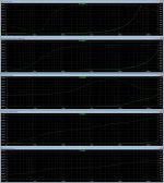
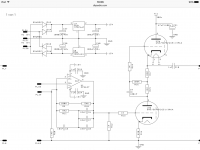
Following my research between top notch regulators, this time I compared output impedances.
The name of each regulator is on the upper right.
Some similar limits were introduced to make the comparison valid, in horizontal frequency and in vertical mili ohms.
Some results were so low, that a new comparison might necessary to raise them somehow, or adding the numbers in characters for comparisons.
The NoNoiser seemed to take the maximum honors in Lowest impedance for the bandwidth chosen.
Schematics and asc files are available for checking.
Attachments
Trying to open up my options.
Just did a small search for more regulators that could be used for my +/-30 supply, and I found these two Texas LDOs, ultra-noise, high PSRR chips. For positive and negative regulators.
http://www.ti.com/product/TPS7A49/support
http://www.ti.com/product/TPS7A30
A search on DIYAudio for these regulators didn't return comments on people using them, so maybe there were issues with them.
Any comments?
I use these regs in several designs and also have sold several dozens of PCBs using them. So far I haven't experienced any issues with these regs.
Have a look here, here and here for more info
Regards,
Oleg
Thanks, Oleg. Very interesting.
Do you know if someone simulated these regulators in LTSpice?
Other simulations won't do, because I can't use them.
Couldn't find any models for the regulators, which would be the key parts.
Has anyone provided curves for PSRR, impedance and noise for those regulators.
Definitely not interested in the DC-DC version, only linear one.
Trying to open up my options.
Just did a small search for more regulators that could be used for my +/-30 supply, and I found these two Texas LDOs, ultra-noise, high PSRR chips. For positive and negative regulators.
http://www.ti.com/product/TPS7A49/support
http://www.ti.com/product/TPS7A30
A search on DIYAudio for these regulators didn't return comments on people using them, so maybe there were issues with them.
Any comments?
I use also TPS regulators for my riaa hybride preamp. They are super.
Attachments
Last edited:
- Status
- This old topic is closed. If you want to reopen this topic, contact a moderator using the "Report Post" button.
- Home
- Amplifiers
- Power Supplies
- Looking for a good power supply for a RIAA preamp