The idea of using an opamp to regulate its own supplies is not completely new, and a few examples can be found in the application literature of some special amplifiers, like the LM3900 Norton amp or the open collector series TAA86x, but here the concept is more general, and also more radical: the opamp directly regulates its own supply in a shunt fashion, without any interface.
This can be used for standalone circuits, but the main interest is to use one amplifier of a multiple package to regulate the common supply.
Why not just use a zener or a classic voltage regulator?
Sometimes, the supply is used as a reference, and needs to be of a better standard than what these simple solutions can offer.
How does it work?
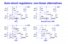
The principle is to tie the output to one of the supply rails, and operate the output stage in single-ended, Class A mode.
This can be done in a number of ways, as this sheet demonstrates:
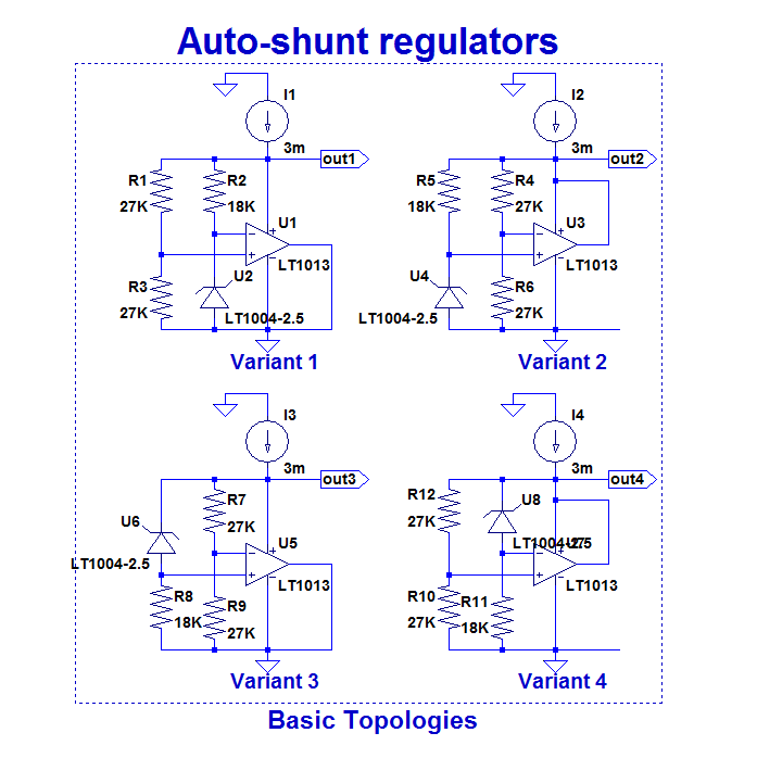
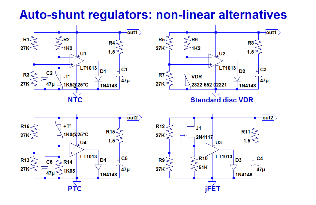
The input circuitry is basically a bridge, having one (or more) non-linear element.
The examples use a voltage reference, but any element having a concave V/I characteristic like a junction could also be used.
If the non-linear element has a convex characteristic, one of the resistors has to be swapped for the non-linear element, but the mode of operation remains the same.
These circuits are incestuous to a high degree: not only does the opamp regulate its own supply, but this supply also biases the reference.
This could cause self-starting issues, but it also means that the whole circuit operates in a complete stasis, yielding an extreme degree of accuracy and performance.
Of course, these simplified examples are too brutal to work in reality: one of the problem is the direct connection of the output to a supply rail: for example, even when its output is supposed to be in a saturated low state, an opamp does not like having it directly and externally shorted to the - rail: it might misbehave, consume lots of current, etc.
Then, there is the issue of bypassing: a supply should be bypassed, but connecting a decoupling cap between the rails will result in capacitive loading, something opamps do not like.
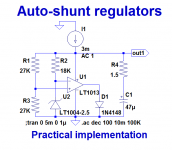
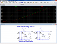
Therefore, a practical circuit needs some adaptations:
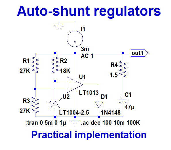
A diode is added in the output to allow it some breathing space, and a low-impedance RC network is used as a bypass.
I will discuss these choices later.
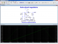
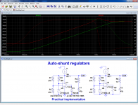
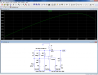
This picture shows the performance of the example circuit (impedance):
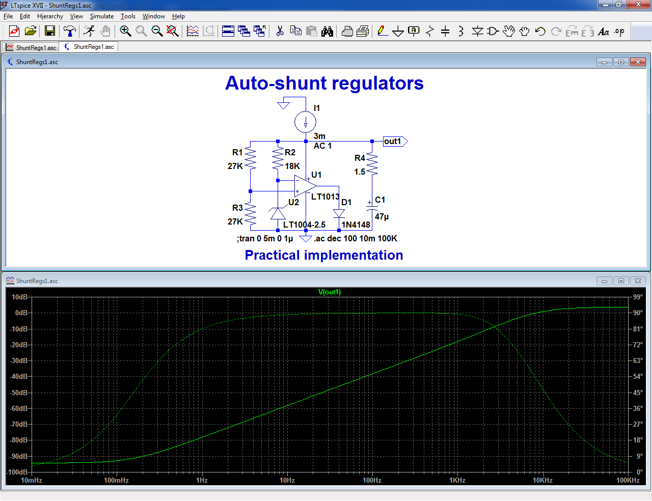
The -94dB at LF/DC is equivalent to a ~20µΩ impedance, which is unusual for such a simple circuit biased at only 3mA.
The rest of the curve follows the GBW characteristic of the opamp, up to the resonance frequency at ~10kHz, determined by the opamp and the 47µF bypass cap.
Beyond 10kHz, the impedance assumes the value of the 1.5Ω damping resistor
This can be used for standalone circuits, but the main interest is to use one amplifier of a multiple package to regulate the common supply.
Why not just use a zener or a classic voltage regulator?
Sometimes, the supply is used as a reference, and needs to be of a better standard than what these simple solutions can offer.
How does it work?
The principle is to tie the output to one of the supply rails, and operate the output stage in single-ended, Class A mode.
This can be done in a number of ways, as this sheet demonstrates:
The input circuitry is basically a bridge, having one (or more) non-linear element.
The examples use a voltage reference, but any element having a concave V/I characteristic like a junction could also be used.
If the non-linear element has a convex characteristic, one of the resistors has to be swapped for the non-linear element, but the mode of operation remains the same.
These circuits are incestuous to a high degree: not only does the opamp regulate its own supply, but this supply also biases the reference.
This could cause self-starting issues, but it also means that the whole circuit operates in a complete stasis, yielding an extreme degree of accuracy and performance.
Of course, these simplified examples are too brutal to work in reality: one of the problem is the direct connection of the output to a supply rail: for example, even when its output is supposed to be in a saturated low state, an opamp does not like having it directly and externally shorted to the - rail: it might misbehave, consume lots of current, etc.
Then, there is the issue of bypassing: a supply should be bypassed, but connecting a decoupling cap between the rails will result in capacitive loading, something opamps do not like.
Therefore, a practical circuit needs some adaptations:
A diode is added in the output to allow it some breathing space, and a low-impedance RC network is used as a bypass.
I will discuss these choices later.
This picture shows the performance of the example circuit (impedance):
The -94dB at LF/DC is equivalent to a ~20µΩ impedance, which is unusual for such a simple circuit biased at only 3mA.
The rest of the curve follows the GBW characteristic of the opamp, up to the resonance frequency at ~10kHz, determined by the opamp and the 47µF bypass cap.
Beyond 10kHz, the impedance assumes the value of the 1.5Ω damping resistor
Attachments
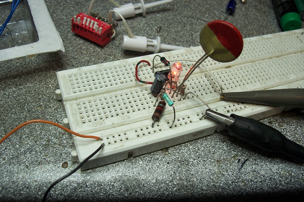
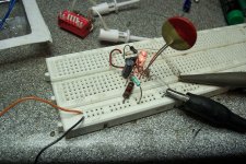
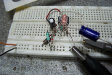
It does, and I have been using this scheme for more than ten years:Seems to be an interesting idea. Over the simulation, a simple breadboard and a humble LM324 can confirm in the practice, if the circuit performs as wanted/expected.
The IC in the test circuit is actually a LM358 (and the non-linear element a VDR)
Attachments

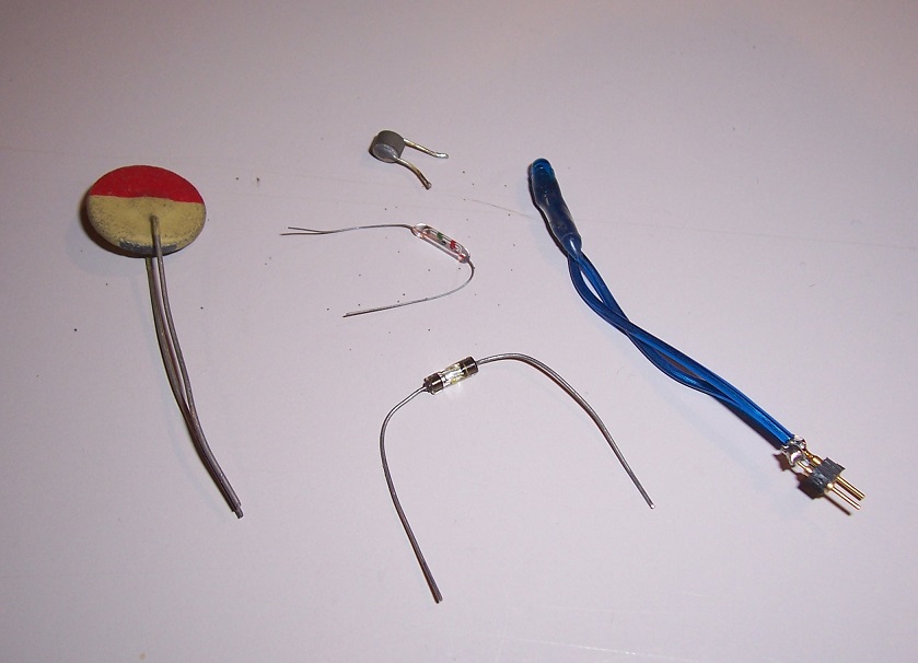
I mentioned in the introductory post that any non-linear element (or combination thereof) can be used.
Here is a selection of concave and convex non-linear elements, beyond the too obvious forward-biased diode, LED, shunt ref, zener, etc:
It is perfectly possible to use NTC's, PTC's, old-style VDR's, etc.
All of these examples are dimensioned for a 5V output
Note that a tungsten light bulb makes an excellent PTC.
Here is a selection of examples including such components, including a tiny 2.5V 20mA light bulb:
When the non-linear element has a significant time-constant compared to the opamp, it is necessary to include some kind of frequency compensation: that is the role of the 47µF in the schematics, used with thermal elements.
Here is the circuit with a glass NTC:

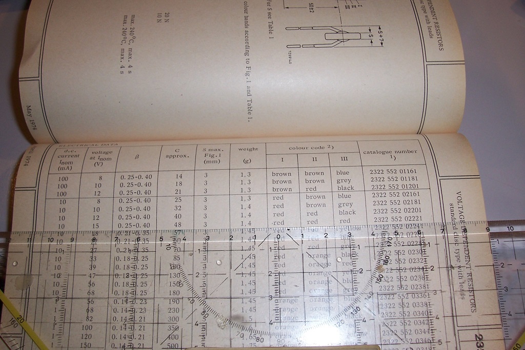
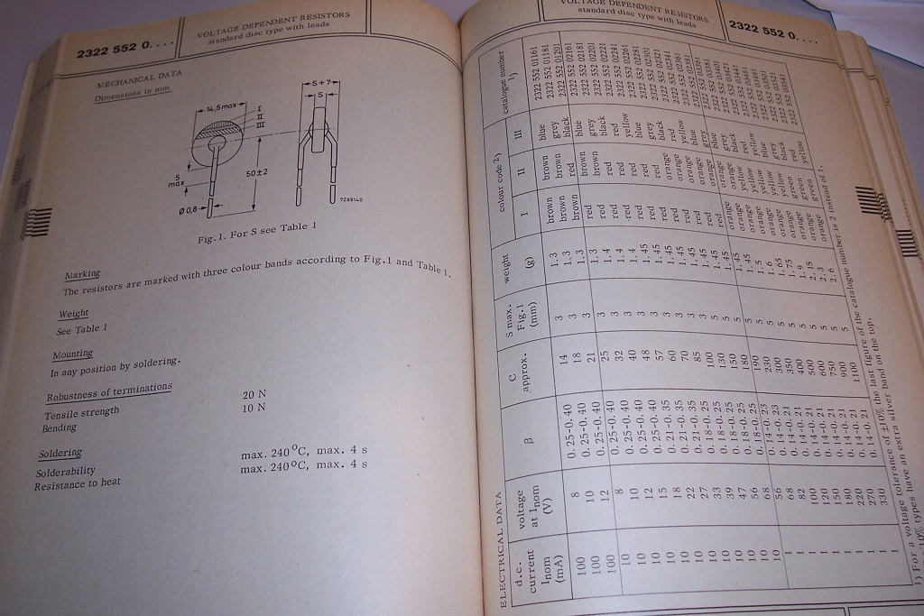
The VDR circuit has been shown above:
Here are the data of the VDR in question:
Here is a selection of concave and convex non-linear elements, beyond the too obvious forward-biased diode, LED, shunt ref, zener, etc:
It is perfectly possible to use NTC's, PTC's, old-style VDR's, etc.
All of these examples are dimensioned for a 5V output
Note that a tungsten light bulb makes an excellent PTC.
Here is a selection of examples including such components, including a tiny 2.5V 20mA light bulb:
When the non-linear element has a significant time-constant compared to the opamp, it is necessary to include some kind of frequency compensation: that is the role of the 47µF in the schematics, used with thermal elements.
Here is the circuit with a glass NTC:
The VDR circuit has been shown above:
Here are the data of the VDR in question:
Attachments


I can see the benefit of saving a regulator when you have a spare section in a dual or quad package, but I'd use an output resistor or zener, not diode, in order to put the output voltage further from the rail and get better performance, since output close to a rail is very compromised in many rail-to-rail opamps (they only tell you that further down the datasheet!)
I said earlier that I was going to discuss this issue: now is the time.but I'd use an output resistor or zener, not diode, in order to put the output voltage further from the rail and get better performance, since output close to a rail is very compromised in many rail-to-rail opamps (they only tell you that further down the datasheet!)
Many options are usable to allow the output to work properly, and they include resistors, LEDs, zener, etc.
In my breadboard prototype I have used a LED, because it also allows a visual health-check of the good operation: it visualizes the shunt current.
At first sight, a resistor would look like a good (and cheap) choice, however it has a number of drawbacks:
One is that the shunt current will never be able to go to zero, except for a good R-to-R opamp: with a typical standard opamp having a residual voltage of 1Vbe, a leakage current of ~0.6/R will always be present, even if the regulator doesn't need to shunt any current.
Of course, you can increase the resistor's value, but if it is too large, it will limit the maximum possible shunt current.
But these are relatively minor issues: the main problem with a resistor is elsewhere: it will eat up a large portion of the available loop gain, thus decreasing the performances significantly.
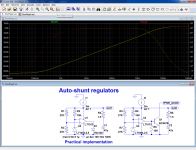
To illustrate this point, here is a comparison between the diode and resistor versions:
The performances are down by more than 20dB.
Regarding the performances of an opamp working close to its rails, they have to be judged in the context: SE, class A, and not regular class AB operation.
In fact, only one of the transistors of the output PP is actually active, and it works at its best when its Vce is close to the total supply available.
Tying it directly to one rail is generally not an option, because it upsets the bias circuitry, but going as close as possible (with a margin) poses no particular problem.
Note that each case is different, and depending on the exact opamp, the drop of 1 schottky diode might be sufficient whilst others require 1, 2, 3 or even more Vbe's.
The LT1013 is already happy with one schottky for the negative rails, but it requires at least 2 Vbe for the +rail.
Also note that depending on the behavior of the opamp at very low supply voltage and/or when its common mode range is exceeded, the circuit might fail to start properly.
However, if one of the rails doesn't work, the other will generally be OK: there are 4 variants to chose from.
If the output junction is the B-E of a transistor, its collector will deliver a convenient /PWR_GOOD signal when the circuit begins to regulate:
A completely different subject: by adding one capacitor, it is possible to improve the AC performances.
When the division ratio of the bridge is moderate, like here, it doesn't bring great improvements, but if the non-linear element is a light bulb for example, it could make a large difference:
Attachments
At this stage, you might wonder: this circuit is very nice and clever, and does unusual things in an unusual way, like turning improbable elements like a very soft, +300ppm/°C PTC into an incredibly stiff 5V voltage/reference, but what's the point?
A TL431 does more or less the same kind of job (not with a thermistor though), costs almost nothing and integrates in a single package the equivalent of the opamp and the three associated discretes.
There are many possible answers: I already mentioned one, the performance.
With a reasonably good opamp, you can get vastly superior performance.
Another is current consumption: the example of 1/2 LT1013 or LM358 plus the additional components already consumes less power than a regular 431, yet the circuit has not been optimized with this aspect in mind.
Flexibility can also be a valuable asset: with a 431, the feedback is referenced to the negative side.
If you want to modulate this reference is some ways, it can be more advantageous to use a + referenced circuit.
You can use any type of reference, provided it is only vaguely non-linear: this can be handy in certain types of situations, where thermal compensation is also necessary.
And finally, it just adds another string to your bow: it is good to have a wide range of solutions to chose from, and this will always prove useful at one time or another: I have developed the concept more than a decade ago, and I have been using it on more than one occasion.
Here is another example: it is a bandgap regulator/reference on a shoestring, using only two ordinary diodes and operating at a micropower level, drawing around 140µA:
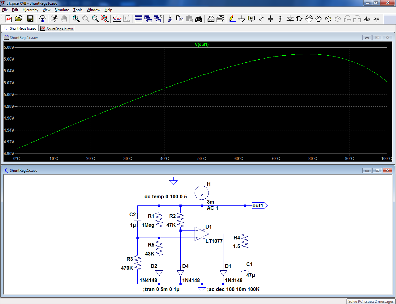
It is only made possible thanks to the bridge configuration, reaching the exact equilibrium for a 5V output and a zero tempco.
Of course, with gold-doped diodes, you are not going to extrapolate this circuit into nA levels, but with more ideal diodes like 1N646 or transistor junctions, it could be possible.
Have fun!
A TL431 does more or less the same kind of job (not with a thermistor though), costs almost nothing and integrates in a single package the equivalent of the opamp and the three associated discretes.
There are many possible answers: I already mentioned one, the performance.
With a reasonably good opamp, you can get vastly superior performance.
Another is current consumption: the example of 1/2 LT1013 or LM358 plus the additional components already consumes less power than a regular 431, yet the circuit has not been optimized with this aspect in mind.
Flexibility can also be a valuable asset: with a 431, the feedback is referenced to the negative side.
If you want to modulate this reference is some ways, it can be more advantageous to use a + referenced circuit.
You can use any type of reference, provided it is only vaguely non-linear: this can be handy in certain types of situations, where thermal compensation is also necessary.
And finally, it just adds another string to your bow: it is good to have a wide range of solutions to chose from, and this will always prove useful at one time or another: I have developed the concept more than a decade ago, and I have been using it on more than one occasion.
Here is another example: it is a bandgap regulator/reference on a shoestring, using only two ordinary diodes and operating at a micropower level, drawing around 140µA:
It is only made possible thanks to the bridge configuration, reaching the exact equilibrium for a 5V output and a zero tempco.
Of course, with gold-doped diodes, you are not going to extrapolate this circuit into nA levels, but with more ideal diodes like 1N646 or transistor junctions, it could be possible.
Have fun!
Attachments
- Status
- This old topic is closed. If you want to reopen this topic, contact a moderator using the "Report Post" button.
- Home
- Amplifiers
- Power Supplies
- Opamps self-supply with AutoShunt regulators