Hello,
Lots of audio equipment requires regulated, low noise power supply. Heres my attempt to design universal, quiet and relativly cheap power supply for those needs.
The idea of making this project came after seeing this thread. Basically, this is PSU part of my headphone amplifier.
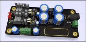
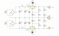
Good old LM317 and LM337 regulators and half wave rectifier. Board can be powered by AC-AC wall wart or transformer. Those wall warts are cheap and easy to use as there is no contact with potentialy dangerous mains wiring.
Voltage at input passes by CLC filter. If desired, inductors can be replaced by 0-10 ohms resistor or even shorted. That would push costs even lower in tradeoff of small performance drop. Regulators are protected by D3 and D4 diodes.
Instead of using more common voltage divider to set output voltage I decided to use zener diodes. Dynamic resistance of zener diode is lower than required resistor which should result in lower output noise. By default 13V zeners yelds about +/- 14.5V at output with less than 10mV diffrence beetwen negative and positive rails. Output voltage can be changed by choosing diffrent zener diodes.
Cadj capacitors are of course present, something from range 10-47uF is recommended. There are two LEDs at both rails. Besides being indicators they run at relatively high current, providing constant load to regulators which keeps low output impedance.
Board measuers 100mm x 45mm. That means cheap PCB fabs like JLCPCB can be used. Latout PDF printed at A4 paper should be 1:1 of board size.
All required files such as schematics, BOM and gerbers are attached to post.
I'm open on any suggestions or improvements.
Lots of audio equipment requires regulated, low noise power supply. Heres my attempt to design universal, quiet and relativly cheap power supply for those needs.
The idea of making this project came after seeing this thread. Basically, this is PSU part of my headphone amplifier.
Good old LM317 and LM337 regulators and half wave rectifier. Board can be powered by AC-AC wall wart or transformer. Those wall warts are cheap and easy to use as there is no contact with potentialy dangerous mains wiring.
Voltage at input passes by CLC filter. If desired, inductors can be replaced by 0-10 ohms resistor or even shorted. That would push costs even lower in tradeoff of small performance drop. Regulators are protected by D3 and D4 diodes.
Instead of using more common voltage divider to set output voltage I decided to use zener diodes. Dynamic resistance of zener diode is lower than required resistor which should result in lower output noise. By default 13V zeners yelds about +/- 14.5V at output with less than 10mV diffrence beetwen negative and positive rails. Output voltage can be changed by choosing diffrent zener diodes.
Cadj capacitors are of course present, something from range 10-47uF is recommended. There are two LEDs at both rails. Besides being indicators they run at relatively high current, providing constant load to regulators which keeps low output impedance.
Board measuers 100mm x 45mm. That means cheap PCB fabs like JLCPCB can be used. Latout PDF printed at A4 paper should be 1:1 of board size.
All required files such as schematics, BOM and gerbers are attached to post.
I'm open on any suggestions or improvements.
Attachments
Hi BamboszeK,
I have a couple of suggestions to your layout. I would recommend to replace the output electrolytics with 1uF ceramic caps near the regs out pins. The 220uF output caps do nothing in the position where they are now. You are also missing a pair of reverse bias protection diodes between C_adj and regs output.
To make the PCB smaller you can move the output connector to the shorter edge of the PCB (between the mount holes). This will make the PCB ~1cm smaller in width and smaller bards are easier to fit into tight spaces. The indicator LEDs can be moved to the long edges of the PCB near the regs and made SMD to save even more space. You can probably use 3 pin output connector too.
The GND plane should ideally cover the supply traces to the input filter caps. I would simply make the GDN plane under the entire board.
Hope it helps.
Regards,
Oleg
First of all I would like to thank you for your input. I ommited Cadj discharge diodes as they are usually not mandatory. They are only required for high voltage operation (such as +/- 25V) or capacity much bigger than 10uF.
Choosing output capacitors is the tricky part. LM317/LM337 are almost 50 years old now. Back then capacitors had much higher ESR and ceramic capacitors were nowhere near uF range. They need some series resistance to be stable. LM317 is almost always stable, even without any Cout. LM337 is much more picky. Most manufactuers don't recommend direct connection to ceramic or low ESR capacitors at output. It differs from manufactuer to manufactuer, some are happy some are not. I don't like idea of small series resistor (like 0R1) so decided to include footprints for electrolytics. 220uF value isn't really that important, anything what fits would be ok. Preferrably cheapest series to keep ESR high. They can be even ommited if there is capacitor at powered board already.
I've been thinking about moving connector to front side of PCB and LEDs eslewhere but latter abbandoned this idea. That would make really tight fit between terminal block and radiators. Presonally I prefer thu hole LEDs. Much easier to move them off-board and most of DIYers have lots of them laying around. Board might be a bit smaller but I don't think that even 45mm would be a problem. 4 pin terminal block was choosen becouse it is easier to route four twisted wires rather than three. Some terminal blocks struggle to hold two thick GND wires at once and it helps to keep parts count down (3x 2p terminal instead of 1x 2p and 1x 3p)
The output capacitor does affect the noise, and peaking.
Simple Voltage Regulators Part 1: Noise - [English]
Simple Voltage Regulators Part 1: Noise - [English]
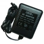
As this power supply uses half wave rectifier you would need transformer with single secondaries. Voltage of 14 to 16 volts would be perfect.
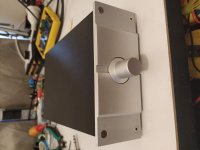
Personally I'm using something like one on the photo. I can get them cheap locally. Less than 2 USD, safe and easy to use.
Personally I'm using something like one on the photo. I can get them cheap locally. Less than 2 USD, safe and easy to use.
Attachments
This board - not. But my headphone amplifier uses exactly same circuit and works rather well ")
High performance OPA1602 + TPA6120A2 Composite Headphone Amplifier
High performance OPA1602 + TPA6120A2 Composite Headphone Amplifier
Last edited:
One change I would make
Since those Zener diodes will be working in avalanche mode(above ~6V is avalanche, below is zener), you'll get a positive tempco from them. . Depending on the brand, you can expect about 10mV per degrees C.
I would use a xx431(which is just a temperature compensated variable zener diode) with decent resistors(.1% 100ppm tempco are not expensive if you look around, the resistors might add 30mV each over the entire range). As an example the NCP431 by On Semi will only drift 15mV max through the temperature range which for the xV series is -40 to +125 C. As a matter of fact they will drift less than the 317/337 will(whereas the plain zeners would be the most driftiness by far).
These also are not expensive if you look for them. I just picked up 10 NCP431BV(.5%, V temp) for $.055 each) less than a week ago.
I will agree that the NCP431BV is not a jellybean part, but the low grade NCP431C comes close(they are about the cheapest of the xx431's) and the common xx431's are. They have been in use forever(released 1978) by a lot of devices including the Apple II, almost all computer power supplies, video games, etc. Just about anyplace that sells LM317/337s will also sell the xx431's.
As for requirements, I should have mentioned that the vast majority of the 431's will have a lower noise than a regular zener. There is a reason why some of the most common commercial noise sources are based on zener diodes.They are also easy to make variable, no need to swap out resistors.
My main concern was the fact that the tempco for zeners suck and in this case are used to directly determine output voltages. Given their location(between the linear regs and caps) a 20 or 30 degree(if not more) rise under load could cause an output variance of .250V or more.
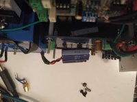
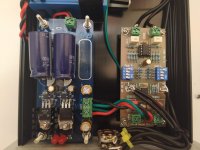
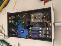
Here's my build used for a Rod ellitot P88 preamp
The capacitors I had on hand were a 50v version and too tall for the case I bent them over on both sides for slim line fit.
The capacitors I had on hand were a 50v version and too tall for the case I bent them over on both sides for slim line fit.
Attachments
I think Elvee's denoiser approach will blow this design out of the water: Post #518
D-Noizator: a magic active noise canceller to retrofit & upgrade any 317-based V.Reg.
The schematic and all of the gerbers files are there; reportedly bringing noise level down to ≤ 2uV on a 15 volt supply.
D-Noizator: a magic active noise canceller to retrofit & upgrade any 317-based V.Reg.
The schematic and all of the gerbers files are there; reportedly bringing noise level down to ≤ 2uV on a 15 volt supply.
I think Elvee's denoiser approach will blow this design out of the water: Post #518
D-Noizator: a magic active noise canceller to retrofit & upgrade any 317-based V.Reg.
The schematic and all of the gerbers files are there; reportedly bringing noise level down to ≤ 2uV on a 15 volt supply.
Yes, it will most certainly do so.
There's also a version called Dienoiser, designed by another member, which gets even better results on LTSpice.
About the output ceramics, except if you are putting them close to what you are powering, do not use them. Do prefer electrolytics at the output, and look they are not too low in ESR.
There's an article in TNT-Audio that also mentions the problem of using output ceramics with this regulator. Close to the bypass pins it's fine.
Do try COGs if you can.
- Home
- Amplifiers
- Power Supplies
- My take on LM317 / LM337 power supply PCB