i have read many thread on this topic. some good some confusing. My question is how to decouple electrolytic capacitor close to integrated circuit(audio amp ICs)?
what is the standard method(simple & effective)?
1)only electrolytic cap alone?
(100uf-1000uf).
2)Traditional high & low esr combo like 100uf-1000uf
+100nf film/ceramic?
3)100uf elec + 1uf film (100:1 ratio).
Regards.
what is the standard method(simple & effective)?
1)only electrolytic cap alone?
(100uf-1000uf).
2)Traditional high & low esr combo like 100uf-1000uf
+100nf film/ceramic?
3)100uf elec + 1uf film (100:1 ratio).
Regards.
There is already at least one active thread on this topic. Here is the gist: some say one thing, others another. Some claim audible differences, some with know how and experimental prowess have showed that they have several disadvantageous effects on PSU impedance. I doubt we need another thread discussing this though...
E.g Adding film caps to psu, any good
And paralleling film caps with electrolytic caps
E.g Adding film caps to psu, any good
And paralleling film caps with electrolytic caps
Last edited:
Depends on the speed of the chip really, fast chips should always have ceramic decoupling very close to the package (because of stray inductance of pcb traces). Bulk decoupling (electrolytic) is slower, so can be further from a chip (and thus shared between chips).
In general you want bulk decoupling with audio to fill in the frequency range between fast ceramic caps and the voltage regulator feedback response bandwidth, especially with old slow linear regulators whose output impedance rises inexorably with frequency.
Decoupling for audio is used for (at least) two distinct purposes - one is to prevent unwanted feedback paths across the pcb via the supply rails, the other is to keep a chip stable by providing low impedance supplies (in fact this acts to prevent unwanted feedback paths within the chip). Here this means low impedance at a wide range of frequencies, including audio and above (where parasitic oscillations might otherwise happen).
The former requirement is typical of high gain amplification where the output signal is much bigger than the input signals (think microphone preamp etc) - even small amounts of signal leaking from output to input through the supply would cause oscillation. With lower gain circuits this is much less critical.
Note that for fast decoupling only multi-layer caps are worth using (low inductance). Ceramics are usually multilayer, films are usually wound (through-hole) or multilayer if SMT chip capacitors. Film caps wouldn't normally be used for decoupling, as their cost more and their linearity isn't important for decoupling.
So with a fast opamp, say, you'd have 100nF ceramic at the chip across the two supply rails for high frequency stability, and somewhere nearby the rails might be decoupled to ground with electrolytics.
For a power amp circuit you'd use ceramic and electrolytic, and you'd pay attention to where the decoupling caps are sited - substantial non-linear currents flow in decoupling of a power amp and these need to be kept away from sensitive parts of the circuit, using appropriate star-grounding layout.
What sort of audio amp IC? Opamp? Power amp? DAC? Digital filter?
You haven't actually told us anything to help us help you.
As a general principle, capacitors do not need to be 'bypassed' or 'decoupled'. What may sometimes be helpful is a low value film or ceramic cap with short leads right on the device supply rail pins, and an electrolytic somewhere on the same PCB. Be guided by the chip datasheet. You can ignore 50% of the advice you will read on audio forums; the snag is that you might not be able to determine which 50%.
You can ignore 50% of the advice you will read on audio forums; the snag is that you might not be able to determine which 50%.
Some good information is free -- this piece on decoupling from Analog Devices:
https://www.analog.com/media/en/training-seminars/tutorials/MT-101.pdf
Eva says the same (good quality switching type electrolytic). But according to some people dual winding with double bridge rectification can eliminate all a.c residual.
i think i should start from 100-1000uf general purpose electrolytic with 1uf film(mkt), because currently i don't have x7r or mlcc ceramics & switching type electrolytic.
i think i should start from 100-1000uf general purpose electrolytic with 1uf film(mkt), because currently i don't have x7r or mlcc ceramics & switching type electrolytic.
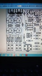
Attachments
I want to make things a little bit clearer.But according to some people dual winding with double bridge rectification can eliminate all a.c residual.
Double bridge rectification itself can't help with the elimination of AC residual, but it definitely helps with good and right PCB-design, which leads to lower AC residual (in common wire and so on).
I want to make things a little bit clearer.
Double bridge rectification itself can't help with the elimination of AC residual, but it definitely helps with easy and good PCB-design, which leads to lower AC residual (in common wire and so on).
yes, of course.
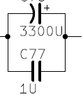
Probably overkill, but it does not break the minimal rules: no paralleling of capacitors having a ratio larger than 1:100.
They do not guarantee the absence of nasty resonances, but at least they do not guarantee their presence.
The rest is very much application-dependent: in fact, the 1:100 rule can be broken, take for example a small logic board located far away from the 1000µF main resevoir cap: not only you can add a 1µF local bypass, but you should.
What you should avoid is direct, indiscriminate paralleling of large ratios capacitors:
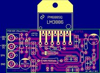
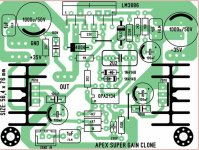
Attachments
Probably overkill, but it does not break the minimal rules: no paralleling of capacitors having a ratio larger than 1:100.
They do not guarantee the absence of nasty resonances, but at least they do not guarantee their presence.
The rest is very much application-dependent: in fact, the 1:100 rule can be broken, take for example a small logic board located far away from the 1000µF main resevoir cap: not only you can add a 1µF local bypass, but you should.
What you should avoid is direct, indiscriminate paralleling of large ratios capacitors:

So you are saying i should go for 1:100 rule? Simple but effective way! if so, then that's what i wanted to hear
")
Do not misinterpret what I said: in general, over-decoupling with >100 ratio brings more problems than benefits, but ideally you should remain well below, 10 to 50 for example.
No misinterpretation .... absolutely not
i understand your words. i know there are no specific criteria & for me it is better not to engage in complexity
Thnks 
- Status
- This old topic is closed. If you want to reopen this topic, contact a moderator using the "Report Post" button.
- Home
- Amplifiers
- Power Supplies
- power supply decoupling