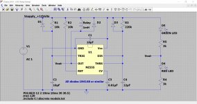
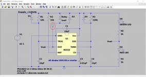
The following circuit is a copy of an LM555 (equiv NE555) based relay delay circuit I designed around 20 years or more ago for muting the output of a preamp. The design goals were reliable operation and the ability for the circuit to give the full mute period if the power supply was cycled quickly on and off. Some recent threads on diyAudio have enquired about such circuits.
The design offered here is done so as more of a 'cookbook' type of design that can be altered and changed to suit individual requirements rather than a fully documented construction project.
Practical points:
1/ Ideally the circuit should be fed from a small auxiliary supply of limited 'reserve' capacity. This means a supply of minimal reservoir capacitor size which ensures that the relay drops out very smartly on power off. A single half wave rectifier and smallish cap (perhaps just 220uF) is the kind of thing that would work well. Ensure the ripple rating of the cap is not exceeded. A little series resistance added to the supply works wonders in dramatically reducing peak ripple currents.
2/ The delay can be altered by means of the time constant of R3 and C4. You should ensure that the combination chosen is suitable. For example it is no good using a 10 Meg resistor and a relatively large and leaky electrolytic cap.
3/ The design has not been tested with either the low power or CMOS versions of the chip. In practice the relatively high draw of the original LM555 can be useful in ensuring the rail powering the device collapses quickly should the power be cycled on/off during the initial period the delay is operating.
4/ The LED indication at the right is something I didn't build into the original, however it could be useful for some. The series connected LED + resistor network seems the simplest method of achieving this and uses the fact that the 555 output switches between supply and ground thus effectively shorting out one or other of the indicators. The series resistors are scaled to suit your LED's.
5/ The original 555 has a wide operating supply range of 5 to 16 volts and a source/sink ability of up to 200ma.
6/ It is very important to decouple the NE555 very close to the power pins in order to avoid false triggering. My favourite approach is to neatly solder a small high quality 10uF cap directly across the pins.
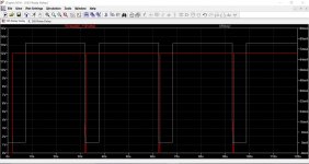
The following images show the circuit diagram, the relay current vs supply voltage in normal operation (the power is on for 1 minute) and finally the behaviour of the circuit in response to rapid cycling of the supply. This is where using a power supply with a small time constant is advantageous.
Edit history...
.asc file updated to enable it to run using default LTspice models.
The design offered here is done so as more of a 'cookbook' type of design that can be altered and changed to suit individual requirements rather than a fully documented construction project.
Practical points:
1/ Ideally the circuit should be fed from a small auxiliary supply of limited 'reserve' capacity. This means a supply of minimal reservoir capacitor size which ensures that the relay drops out very smartly on power off. A single half wave rectifier and smallish cap (perhaps just 220uF) is the kind of thing that would work well. Ensure the ripple rating of the cap is not exceeded. A little series resistance added to the supply works wonders in dramatically reducing peak ripple currents.
2/ The delay can be altered by means of the time constant of R3 and C4. You should ensure that the combination chosen is suitable. For example it is no good using a 10 Meg resistor and a relatively large and leaky electrolytic cap.
3/ The design has not been tested with either the low power or CMOS versions of the chip. In practice the relatively high draw of the original LM555 can be useful in ensuring the rail powering the device collapses quickly should the power be cycled on/off during the initial period the delay is operating.
4/ The LED indication at the right is something I didn't build into the original, however it could be useful for some. The series connected LED + resistor network seems the simplest method of achieving this and uses the fact that the 555 output switches between supply and ground thus effectively shorting out one or other of the indicators. The series resistors are scaled to suit your LED's.
5/ The original 555 has a wide operating supply range of 5 to 16 volts and a source/sink ability of up to 200ma.
6/ It is very important to decouple the NE555 very close to the power pins in order to avoid false triggering. My favourite approach is to neatly solder a small high quality 10uF cap directly across the pins.
The following images show the circuit diagram, the relay current vs supply voltage in normal operation (the power is on for 1 minute) and finally the behaviour of the circuit in response to rapid cycling of the supply. This is where using a power supply with a small time constant is advantageous.
Edit history...
.asc file updated to enable it to run using default LTspice models.
Attachments

You can also try 7555 a CMOS low power and higher frequency capabilities enhanced over the ancient bipolar device.
Thanks Osvaldo. I'm sure it could be made to work with minimal (if any) changes to suit the lower power devices although I would want to test it fully before giving a recommend for those parts.
The source/sink ability is more restrictive, for example the TLC555 quotes 100 mA sink and just 10ma source ability.
The source/sink ability is more restrictive, for example the TLC555 quotes 100 mA sink and just 10ma source ability.
Hi Mooly, could you be kind to explain your circuit more? Why is the relay referenced to v+ instead of ground? Thanks
It is because the 555 output starts off normally high in this configuration and only when the output pin goes low (0 volts) will the relay be powered.
Thank you. I guess theres benefits to be had that way? Ill read around more before deciding on your circuit
Because the pull-down transistor's drive voltage is small, and this way may be close to "common", which in large systems may be simpler or cheaper. Say a 5V logic board and 48V relays.Why is the relay referenced to v+ instead of ground?
Also the most likely place for a fault is a short to chassis or dirt on the wire from transistor to relay. With a low-side relay, when the transistor turns on, it burns-up. With high-side we "only" have unexpected turn-on of the relay. (Which indeed can be dangerous, but circuit designers fret about their circuits more than the guy changing the saw blade.)
There's for/against arguments every which way. Transistors can be protected against shorts. Drive circuits can be floated-up to 48V or even 4,800V. But the assumptions in the '555 go back long before solid-state, to relay systems in telephony and elevators. "Usually" relay coils are high and control switching is to-common.
(Note that I don't say "positive". In telephony the hot, "high", side is normally negative for less trouble with electrolysis in damp windings.)
- Home
- Amplifiers
- Power Supplies
- A universal 'cookbook' relay delay using an LM555 timer.