L-Adapter is aimed at substituting SMPS bricks for whole devices but you people will probably find more uses for it.
Yeah, that's what it was needed. It's just that an extra project got in the way and I had to postpone the Tinker thing a bit and I didn't want to leave the L-adapter just standing there.
I don't expect it will take the place of the Reflektor in this particular DAC but generally as pre regulator could have give have an impact that could bring the overall system sound to someone's liking.
Sound might change a bit since Ele caps must get to the designed spec after long storage time. All semi and resistors are getting to required working points very quickly. I, personally, very skeptical about Burn-in, but defiantly support worm-up. Different subject...
Yes, my DAC is utilizing same chip as Buffalo DAC, which I did not auditioned. So, can’t say anything about compression. The only DAC that I used for comparison is my 9018 based one.
It is day and night in sound, and mostly due to fully independent 3 UntraBIB v1.3 PSUs for Katana components and L-adapter for RPi.
People like “meaty” sound and it is mostly related to the domination of 2nd even harmonic, if not to tweak whole system specifically to achieve such sound. This is typical SE triode tube signature. I like my sound to be bla-bla-bla (marketing nonsense with juicy epithets), but most important for me is realism when I do not see components and imagine performers in front of me.
Oh. I totally forgot. My apology. It was V drop over long thin cables, exactly as you predicted. All is started to work fine when I raised Vout to 5.1V. LCD and HD left connected and my total current fluctuated around 1.8A. It’s impossible to measure Vin on Katana Isolator due to USB type C SMD female connector. Way to small pads for my leads. I lost appropriate once. I’ll get new needle probs soon and might be able to reach these pads soon.
No special specs required because this circuit's stability is not influenced by the output capacitor's ESR. Those caps should be 105C rated though, especially when a board level sink will be used for the main transistor and the output power in some applications will be pushing it to high temperature. Because those caps are at close distance. C1 is located the closest to that heat radiator. Its role is being a filter for the reference voltage.
In comfortable temperature installations those capacitors choice can be broadened to 85C types also. C2 at least which stands further from the sink. As it is the output capacitor and some people may have own preferences for such a location. Think with closed box ambient temperatures in mind if there is a plan of using an enclosure for the project at a later point.
In comfortable temperature installations those capacitors choice can be broadened to 85C types also. C2 at least which stands further from the sink. As it is the output capacitor and some people may have own preferences for such a location. Think with closed box ambient temperatures in mind if there is a plan of using an enclosure for the project at a later point.
I was setting up my own L adapter.
My test transformer secondary is 15Vac (I damaged this transformer so only one pair of 15V secondary winding is working; good for abusive experiment). No load.
Turned on and I saw LED lights and the output Vdc was about 19.9Vdc without adjusting anything yet.
As I switched jumper position, the output Vdc difference is only between 17.xVdc and 19.x Vdc.
Q1: It is supposed to be like this?
And I adjusted the trimpot too quickly and it went down to 7-6-5Vdc etc; both trimpot and LED array unit became extremely hot; then the LED array unit popped.
Q2: What is the relationship between trimpot and jumper setting?
my ultimate goal is to power RPI3...of course.
I got my new transformer-secondary is 2x12Vac.
I will adjust L adapter down to 8Vdc to power the secondary regulatorsx3 (5.1V, 3.3V & 1.8V.)
For the sake of curiosity, I replaced the LED array unit with 10 regular individual LEDs and they worked (leftovers from hotrodded DCB1, good quality clear yellow LEDs from mouser).
Q3: Can the individual LEDs be used in place of the LED array unit?
Sorry too many questions from a newbie
I was setting up my own L adapter.
My test transformer secondary is 15Vac (I damaged this transformer so only one pair of 15V secondary winding is working; good for abusive experiment). No load.
Turned on and I saw LED lights and the output Vdc was about 19.9Vdc without adjusting anything yet.
As I switched jumper position, the output Vdc difference is only between 17.xVdc and 19.x Vdc.
Q1: It is supposed to be like this?
And I adjusted the trimpot too quickly and it went down to 7-6-5Vdc etc; both trimpot and LED array unit became extremely hot; then the LED array unit popped.
Q2: What is the relationship between trimpot and jumper setting?
my ultimate goal is to power RPI3...of course.
I got my new transformer-secondary is 2x12Vac.
I will adjust L adapter down to 8Vdc to power the secondary regulatorsx3 (5.1V, 3.3V & 1.8V.)
For the sake of curiosity, I replaced the LED array unit with 10 regular individual LEDs and they worked (leftovers from hotrodded DCB1, good quality clear yellow LEDs from mouser).
Q3: Can the individual LEDs be used in place of the LED array unit?
Sorry too many questions from a newbie
A1. No it is not supposed to be like this. It should be able to make about 1.75V distance jumps with each deselected LED from all lit highest Vo to very low when only one LED is lit without getting them hot. Confirm about 5mA produced by the current source 334 chip feeding the LEDS and the trimpot. There should only be 64-67mV across R2 if its OK. Check the transistors Vbe to be about 0.6V each. Hot popped parts means excessive current in their circuit branch. Recheck your design's connections against the schematic. Check for the LED bar's beveled orientation corner, it can be tricky to see. Replace any broken parts.
Another precaution is C2 can hold the voltage of a higher setting for a while if there isn't a path to ground (when both unloaded & R1 bleeder is not installed).
A2. The voltage level base are the LEDS. If you set the trimmer to zero it contributes no voltage to the LEDS chain. Expect about 17.5V Vout with all LEDS engaged when trimmer is at zero. So 5mA*500 Ohm means 2.5V max trimmer adjust contribution. That makes for 20V output max if your transformer can support it. Say some 18VAC one. With lower transformer / Vout goal not all LEDS will be able to light up anyway.
Vout as comprised by any chosen lit LEDS number plus whatever extra coming from the trimmer for your adjustment convenience, eventually equals C1's voltage level - 0.6V.
A3. Yes no problem.

One for two. I have the aikido with 4 tubes total. I hooked up one tube with some alligator clips to see if it pushes done current, but only for a little bit. It is 2 past midnight here, A time for some occasional short circuit accidents . Especially when I need to do some creative board placing and wiring to bypass PS-21 heater regulators, but led HV part as those are on the same boards. Really hope that Tea will be able to get your HV boards for coming GB
. Especially when I need to do some creative board placing and wiring to bypass PS-21 heater regulators, but led HV part as those are on the same boards. Really hope that Tea will be able to get your HV boards for coming GB 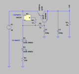
- Home
- Amplifiers
- Power Supplies
- L-Adapter