Just updated REW, had to recalibrate, a 1Vrms input signal was -20dBV down instead of 0dBV. After recalibrating, REW displays 34.52V as the "FS Sine Vrms" value. Correct value would be 3.452Vrms. Might need another update, decimal off one place to the right in some software line. Also explains why after updating it was -20dBV down.
Playing with LTSpice I noticed that using BC807/BC817 pair for the discrete supplies with dienoiser should offer and even lower noisefloor, than with BC337/BC327 pair. So I replaced the BC337/BC327 with the BC807/BC817 pair and indeed the noisefloor measured lower.
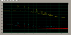
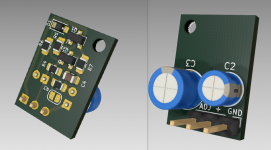
I then decided to measure the smd board as I didn't do that after I calibrated my ADC. So I measured with the smd version of LM317N on the dual smd board, 470uF+100uF input capacitance, 270R load, 12.8Vout.
PSRR values:
denoiser - 113.1dB
dienoiser - 132.5dB
Noise values:
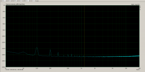
denoiser -166.4dBV so around 4.8nV/sqrtHz
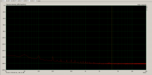
dienoiser -181.11dBV so around 0.88nV/sqrtHz
The board was shielded in a metal case. So the BC8x7 do measure with a bit lower noisefloor.
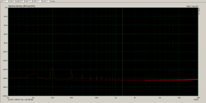
I then replaced the BC3x7 with BC8x7 on the THT LM317N board, 470uF input capacitance, 11.3Vout, 150R load. Noise came out at -165dBV so around 5.6nV/sqrtHz and dienoiser at -178.7dBV so 1.16nV/sqrtHz.
Compared to a previous measurement with BC3x7 the difference is 0.1nV/sqrtHz lower for denoiser and 0.24nV/sqrtHz lower for dienoiser. And the most difference I got was with the discrete regulator + dienoiser, I measured 0.84nV/sqrtHz with BC8x7 and 1.21nV/sqrtHz with BC3x7. But the discrete board was as well as the THT LM317 board without shielding.
In conclusion seems that using BC8x7 instead of the BC3x7 pair results in a lower noisefloor overall. Better gear would be needed for the real numbers, with a shielded board.
First photo is PSRR for smd board with LM317N.
Second photo is denoiser noise for smd board.
Third photo is dienoiser noise for smd board.
Fourth and fifth are measurements for THT LM317N noise for denoiser and dienoiser with BC8x7 instead of BC3x7.
The archive contains the measurements for smd LM317N on the dual smd board.
I then decided to measure the smd board as I didn't do that after I calibrated my ADC. So I measured with the smd version of LM317N on the dual smd board, 470uF+100uF input capacitance, 270R load, 12.8Vout.
PSRR values:
denoiser - 113.1dB
dienoiser - 132.5dB
Noise values:
denoiser -166.4dBV so around 4.8nV/sqrtHz
dienoiser -181.11dBV so around 0.88nV/sqrtHz
The board was shielded in a metal case. So the BC8x7 do measure with a bit lower noisefloor.
I then replaced the BC3x7 with BC8x7 on the THT LM317N board, 470uF input capacitance, 11.3Vout, 150R load. Noise came out at -165dBV so around 5.6nV/sqrtHz and dienoiser at -178.7dBV so 1.16nV/sqrtHz.
Compared to a previous measurement with BC3x7 the difference is 0.1nV/sqrtHz lower for denoiser and 0.24nV/sqrtHz lower for dienoiser. And the most difference I got was with the discrete regulator + dienoiser, I measured 0.84nV/sqrtHz with BC8x7 and 1.21nV/sqrtHz with BC3x7. But the discrete board was as well as the THT LM317 board without shielding.
In conclusion seems that using BC8x7 instead of the BC3x7 pair results in a lower noisefloor overall. Better gear would be needed for the real numbers, with a shielded board.
First photo is PSRR for smd board with LM317N.
Second photo is denoiser noise for smd board.
Third photo is dienoiser noise for smd board.
Fourth and fifth are measurements for THT LM317N noise for denoiser and dienoiser with BC8x7 instead of BC3x7.
The archive contains the measurements for smd LM317N on the dual smd board.
Attachments

Denoiser Add-on Implementation
I have posted about this project before, but I did not have my measurement system calibrated. These measurements are correct. The unit that had the add-on boards installed was a Hafler DH-110 preamplifier.
Noise positive rail = -170.99dB or 2.8nV/sqrtHz @1kHz
PSRR@120 Hz positive rail = -78.76dB not the best, but everything below -135dB.
Noise negative rail = -169.16dB or 3.4nV/sqrtHz @1kHz
PSRR@120Hz negative rail = -79.11dB, not real good, but again everything below -135dB.
Positive Rail Noise

Positive Rail Output Ripple

Positive Rail Input Ripple

Negative Rail Noise

Negative Rail Output Ripple

Negative Rail Input Ripple

These measurements were taken with the add-on boards installed. The negative rail had to have a Panasonic FR series 470uF/35V capacitor added to get the denoiser to work. The Hafler uses 8 capacitors per rail, up and down the rail near each section.
Add-on Board Installation

Panasonic Capacitor added on back of circuit board

I have posted about this project before, but I did not have my measurement system calibrated. These measurements are correct. The unit that had the add-on boards installed was a Hafler DH-110 preamplifier.
Noise positive rail = -170.99dB or 2.8nV/sqrtHz @1kHz
PSRR@120 Hz positive rail = -78.76dB not the best, but everything below -135dB.
Noise negative rail = -169.16dB or 3.4nV/sqrtHz @1kHz
PSRR@120Hz negative rail = -79.11dB, not real good, but again everything below -135dB.
Positive Rail Noise
Positive Rail Output Ripple
Positive Rail Input Ripple
Negative Rail Noise
Negative Rail Output Ripple
Negative Rail Input Ripple
These measurements were taken with the add-on boards installed. The negative rail had to have a Panasonic FR series 470uF/35V capacitor added to get the denoiser to work. The Hafler uses 8 capacitors per rail, up and down the rail near each section.
Add-on Board Installation
Panasonic Capacitor added on back of circuit board
You can get the model from here: https://www.ti.com/product/LM317-N#design-development##design-tools-simulation
What about LM338? It is fully compatible with LM317 circuit? Can't seem to find model aswel.
RickRay, what Vout? Higher than 12V would explain the even lower noise of the BC817 with denoiser.
The LM338 is compatible but I didn't make any PCB that supports its full current output. You could use it instead of LM317 up to 1.5A.
What about LM338? It is fully compatible with LM317 circuit? Can't seem to find model aswel.
The LM338 is compatible but I didn't make any PCB that supports its full current output. You could use it instead of LM317 up to 1.5A.
Elvee, I was wandering about the decrease in PSRR performance with add-on boards, and also non-ideal layout.
Is it possible that the add-on denoiser sense lines pick up mains ripple that is out of phase with the ripple on the input of the regulator, thus not canceling out on the regulator output?
Is it possible that the add-on denoiser sense lines pick up mains ripple that is out of phase with the ripple on the input of the regulator, thus not canceling out on the regulator output?
Trileru, I should have listed that. The Hafler uses +/- 23.1VDC rails, so the higher voltage, less noise.
Yes, it is is perfectly possible if the GND and sense lines enclose a significant loop area, and if that area is subject to parasitic magnetic fields.Is it possible that the add-on denoiser sense lines pick up mains ripple that is out of phase with the ripple on the input of the regulator, thus not canceling out on the regulator output?
Whenever possible, the sense line should be as close (or twisted) to the GND, up to the point of use.
In the vicinity of the power transformer and rectifier/filter caps, there are always significant magnetic perturbations.
Upstream of the bridge rectifier, there will be mostly harmonics of the mains frequency and downstream 2*Fmains harmonics.
The phase depends on many factors, but in general the mag field caused by the charging spikes will be out of phase with the ripple voltage.
Thank you for the info!
Do you think you can test BC817 with denoiser for noise? In my tests it seems to perform better than BC337. But I don't have the gear to measure it's lowest noise.
Also I noticed that as opposed to LM317+denoiser, both discrete supplies have actually a bit lower noisefloor with just the denoiser instead of dienoiser. I remember you mentioning that with LM317+denoiser the output noise depends on the LM317 noise as well, and with dienoiser the noise depends solely on the dienoiser circuit transistors.
Since RickRay tested the add-on board and since the first version I got a better grip on the part values that work best I decided to update both add-on board designs a bit.
They are still diy-able, one smd one tht. Now there's only one jumper on each to switch between denoiser and dienoiser.
The dienoiser resistor should always be 560R, a good compromise, always worked for me with different Vout.
The 1.8k/180k combo is good for around 12V. For 5V 820/82k should be used, for 25Vout around 3.3k/330k.
There's an RC compensation network on both boards. The tht one has smd and tht footprints for these parts. I recommend 47nF/3.3R combo for both rails, it usually worked for me.
This would be rev 1.1 for both boards.
Attachments

Thank you for the info!
Do you think you can test BC817 with denoiser for noise? In my tests it seems to perform better than BC337. But I don't have the gear to measure it's lowest noise.
I have to search my stock, I am not certain I have BC817's.
Anyway, the 817 should just be a 337 crystal in a SOT23 case.
It could be that your 817's are more recent than the 337, and that could make some difference. In fact, cheap generic chinese S8050's test better than 10~15 years old 337's.
That's normal: the 317 has a significant self noise, and the gain of a denoiser brings it in the region of the transistor noise floor.Also I noticed that as opposed to LM317+denoiser, both discrete supplies have actually a bit lower noisefloor with just the denoiser instead of dienoiser. I remember you mentioning that with LM317+denoiser the output noise depends on the LM317 noise as well, and with dienoiser the noise depends solely on the dienoiser circuit transistors.
Depending on the specifics, one or the other might dominate, but the discrete reg has a lower noise, and the end result is always dominated by the denoiser transistor
Trileru,
thank you for update
would you please confirm that this Is original Elvee Diego de dienoiser add on for LM317 and this pcb Is shown In RickRay post
thank you for update
would you please confirm that this Is original Elvee Diego de dienoiser add on for LM317 and this pcb Is shown In RickRay post
Since RickRay tested the add-on board and since the first version I got a better grip on the part values that work best I decided to update both add-on board designs a bit.
They are still diy-able, one smd one tht. Now there's only one jumper on each to switch between denoiser and dienoiser.
The dienoiser resistor should always be 560R, a good compromise, always worked for me with different Vout.
The 1.8k/180k combo is good for around 12V. For 5V 820/82k should be used, for 25Vout around 3.3k/330k.
There's an RC compensation network on both boards. The tht one has smd and tht footprints for these parts. I recommend 47nF/3.3R combo for both rails, it usually worked for me.
This would be rev 1.1 for both boards.
Yes the smd one is the one that RickRay used. I just removed two parts and two jumpers that were not needed.
Also one thing that RickRay found, you'd have higher chances of stability by using a 22R protection resistor, instead of the 47R that is in the original schematic. The one in series with the 22uF cap that senses the noise. I usually used 10R-22R there. That improves the PSRR a bit as well. 47R seems a bit too high in some cases.
For the smd board if you only have 47R resistors you can add another one in parallel on top of the first.
For the smd board if you only have 47R resistors you can add another one in parallel on top of the first.
Last edited:
I have to search my stock, I am not certain I have BC817's.
Anyway, the 817 should just be a 337 crystal in a SOT23 case.
It could be that your 817's are more recent than the 337, and that could make some difference. In fact, cheap generic chinese S8050's test better than 10~15 years old 337's.
Yes possible, I don't know where I got the BC337 from.
The BC817 did perform a bit better, especially in the discrete designs.
LTSpice shows higher performance for BC817. Aren't both BC337 and BC817 native models?
please point out where are R1 and C1 from back of tht pcb D-Noizator: a magic active noise canceller to retrofit & upgrade any 317-based V.Reg.
Also one thing that RickRay found, you'd have higher chances of stability by using a 22R protection resistor, instead of the 47R that is in the original schematic. The one in series with the 22uF cap that senses the noise. I usually used 10R-22R there. That improves the PSRR a bit as well. 47R seems a bit too high in some cases.
For the smd board if you only have 47R resistors you can add another one in parallel on top of the first.
Last edited:
Elvee said:I have to search my stock, I am not certain I have BC817's.
Anyway, the 817 should just be a 337 crystal in a SOT23 case.
It could be that your 817's are more recent than the 337, and that could make some difference. In fact, cheap generic chinese S8050's test better than 10~15 years old 337's.
I have measued some BC817 transistors. They are much closer to BC550's than to BC337's.
In post 2096 the calibration in ARTA and REW was mentioned:
https://www.diyaudio.com/forums/pow...it-upgrade-317-based-reg-210.html#post6552577
Since I am only a beginner in ARTA, it would be interesting to know how measurements in ARTA were done reliably beyond -120dB.
Even an Audio Precision may not achieve a noise floor beyond -120dB. See for instance: APx555 - High Performance Audio Analysis - YouTube
Information on ARTA is only modestly available: among others, on the site rappie.jouwweb.nl (the text is still only in Dutch. No affiliation).
Can someone please elaborate?
please point out where are R1 and C1 from back of tht pcb D-Noizator: a magic active noise canceller to retrofit & upgrade any 317-based V.Reg.
C1 from the THT board is C4 from the schematic in the post you mentioned. R1 is not included in that schematic, but is included in mine.
The THT board has C4 and R7 as THT compensation netwok. C4 is in parallel with C1 and R7 is in parallel with R1. R1 and C1 are smd 0805 footprints. This way you can use film or ceramic tht or smd caps. I basically added tht and smd footprints for the RC compensation network. For flexibility.
- Home
- Amplifiers
- Power Supplies
- D-Noizator: a magic active noise canceller to retrofit & upgrade any 317-based VReg