@Elvee
I was looking at this thread of yours: https://www.diyaudio.com/community/threads/taming-a-boosted-negative-regulator.369936/
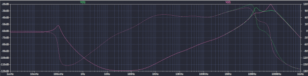
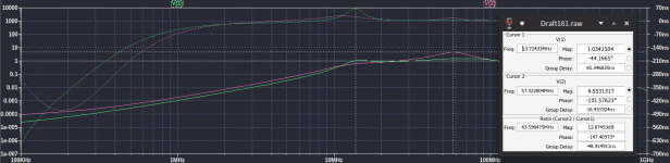
And I tried adding 10uH on the emitter of Q4.

Seems to be working somewhat. I used MJE15033 as pass transistor, figured it's a 8A part and would allow more than the stock 1.5A of LM337. BD139/MJE15033 spice models are from Onsemi's website.
I might try to build and measure it since I have MJE15033. Circuit named 1 is for 4A load and 2 is for 25mA.
edit: also L2 has ~40mA going through it at 4Aout.
I was looking at this thread of yours: https://www.diyaudio.com/community/threads/taming-a-boosted-negative-regulator.369936/
And I tried adding 10uH on the emitter of Q4.
Seems to be working somewhat. I used MJE15033 as pass transistor, figured it's a 8A part and would allow more than the stock 1.5A of LM337. BD139/MJE15033 spice models are from Onsemi's website.
I might try to build and measure it since I have MJE15033. Circuit named 1 is for 4A load and 2 is for 25mA.
edit: also L2 has ~40mA going through it at 4Aout.
Attachments
Last edited:
In reality, it could work -or not- : I can tell you that I tried tried all the tricks of the book to make it work, because opting for a different solution would have been difficult.
In the end, I made it to work -just- .
If a Xnoiser is added, it will further complicate matters, and it will probably be impossible to stabilize.
There is no certitude of course, and only a real-world test can bring a definitive answer, but I am rather pessimistic
In the end, I made it to work -just- .
If a Xnoiser is added, it will further complicate matters, and it will probably be impossible to stabilize.
There is no certitude of course, and only a real-world test can bring a definitive answer, but I am rather pessimistic
Yet the bias of q17 prevents any current being drawn through q17 when the output voltage is too low.At 1.2v output , about 6.4uA is available for biasing the q17 base, but the circuit needs to get at 1.2v output in the first place in a stable manner...Maybe it does with no fast sagging load...I see the circuit stable once it reaches at least 5v output with a fast sagging load. Then lm317 needs to release enough current for boosting trz base..maybe the transistor's leakage helpIf you remove the 2K7 completely and use a reference voltage, a battery or similar to GND, it will work perfectly.
In fact, the 2K7 could be removed completely, but the variations of the Adj current would slightly influence the Vbe of the transistor; the current through the 2K7 swamps the variations completely, because the dynamic resistance of the BE junction is much lower than the recommended 240ohm of the DS with the set current
")
It works in closed-loop: Q17 is just an element in the loop, and as long as the parameters are workable, Q17 will be biased properly.
If there is an incident, like an output short, the conditions will not be met but there is no way to sustain a normal output voltage in those conditions anyway
If there is an incident, like an output short, the conditions will not be met but there is no way to sustain a normal output voltage in those conditions anyway
Ok...so the short by itself will prevent lm317 delivering any current...so it works by accident The way I see it is that apart from your own d'noiser, no other circuit is really using the lm317 chip...so I'd replace it with something cheaper...like tlv431...
The way I see it is that apart from your own d'noiser, no other circuit is really using the lm317 chip...so I'd replace it with something cheaper...like tlv431...
Last edited:
So for more than 1.5A negative output either discrete regulator or dual secondaries with LM338/current boosted LM317 (with denoiser circuit) with inverted connections.In reality, it could work -or not- : I can tell you that I tried tried all the tricks of the book to make it work, because opting for a different solution would have been difficult.
In the end, I made it to work -just- .
If a Xnoiser is added, it will further complicate matters, and it will probably be impossible to stabilize.
There is no certitude of course, and only a real-world test can bring a definitive answer, but I am rather pessimistic
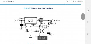
It's easy to make one but useless.Beter build in the air the slow start version , one Ic per tube next to the fillament pins.Thus you get the best noise reduction. Just change R2 for 6.3v or 12.6v output.971 ohms results for 6.3V. You can use the metal chassis usually used with tubes as heatsink.
Attachments
Last edited:
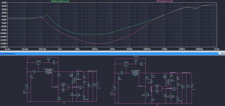
For 6.3Vout and with the current boost circuit it would look something like the attached photo. It's at ~4Aout. But the current boost + denoiser circuit is completely untested.
Depending on the current you could use a LM338+CCS Denoisator/NoNoiser. It worked fine in my tests. It is a 5A rated part after all.
Also Vin is important.
These are also slow-start supplies.
Depending on the current you could use a LM338+CCS Denoisator/NoNoiser. It worked fine in my tests. It is a 5A rated part after all.
Also Vin is important.
These are also slow-start supplies.
Attachments
The 317 does most of the heavy-lifting job; in fact it could be used as some kind of super depletion power ballast. The TL or TLV431 is just a programmable shunt regulator, without any power capability.Ok...so the short by itself will prevent lm317 delivering any current...so it works by accident
The Xnoisers use the power capability of the 317, and its regulating capabilities
I have proposed this circuit: https://www.diyaudio.com/community/...for-high-current-consumer.329949/post-5603233There is one schematic for high current to power vacuum tube heaters?
TIA
Felipe
and it has been successfully tested by the member requesting it
I completely failed to see the usefulness of lm317 in the circuit here:The 317 does most of the heavy-lifting job; in fact it could be used as some kind of super depletion power ballast. The TL or TLV431 is just a programmable shunt regulator, without any power capability.
The Xnoisers use the power capability of the 317, and its regulating capabilities
https://www.diyaudio.com/community/...grade-any-317-based-v-reg.331491/post-7204647
Yet I'm pretty sure it can be successfully replaced by tlv431 in that circuit.
A TO-92 LM317 is about twice as cheap as a TO-92 TLV431:
https://eu.mouser.com/ProductDetail/STMicroelectronics/LM317LZ?qs=yAkVQ3mwCG1SXiMDnAr4Bg==
https://eu.mouser.com/ProductDetail/Texas-Instruments/TLV431AILPR?qs=m96fseALk3VfIiObwTn/wg==
Both cheapest of each that is in stock.
https://eu.mouser.com/ProductDetail/STMicroelectronics/LM317LZ?qs=yAkVQ3mwCG1SXiMDnAr4Bg==
https://eu.mouser.com/ProductDetail/Texas-Instruments/TLV431AILPR?qs=m96fseALk3VfIiObwTn/wg==
Both cheapest of each that is in stock.
Many thanks, any other LED similar to QTLP690C?I have proposed this circuit: https://www.diyaudio.com/community/...for-high-current-consumer.329949/post-5603233
and it has been successfully tested by the member requesting it
Regarding the power aspects, yes maybe, but the circuit would need to be completely overhauled: a TL(V)431 needs a positive voltage on its input terminal, contrary to a 317 which requires a negative voltage.I completely failed to see the usefulness of lm317 in the circuit here:
https://www.diyaudio.com/community/...grade-any-317-based-v-reg.331491/post-7204647
Yet I'm pretty sure it can be successfully replaced by tlv431 in that circuit.
This discussion seems sterile, as the circuit it is based on has little merit, and the topologies need to be quite different to work properly.
If you want to propose a circuit based on the TL431, please do it, but trying to include it in this thread is probably not a good idea. In the post #2611, that's exactly what I did
just any standard red LEDMany thanks, any other LED similar to QTLP690C?
Not my intention.I proposed for this topic to be split in three for the basic three topologies that are discussed here because the thread is really difficult to follow and contribute to.It's your call though...If you want to propose a circuit based on the TL431, please do it, but trying to include it in this thread is probably not a good idea. In the post #2611, that's exactly what I did
1.8V - 30mA ?No voltage nor mA?
- Home
- Amplifiers
- Power Supplies
- D-Noizator: a magic active noise canceller to retrofit & upgrade any 317-based V.Reg.