I think I read that class D is about 90% efficient...
Depends on the conditions of course, 90% would be optimal operation point, that you will never sustain on real music.
As I noted, I am more concerned about constant, overhead losses than peak efficiency.
...slew rate of a SMPS...a lot of work needed to evaluate and modify a stock SMPS to work in this mode...
Yes, I have more or less decided it's too complicated for the minimal extra benefit.
So the proposal now is a SMPS central power supply to provide DC to all the active speakers, each amp will then have a switch mode buck down-converter.
This is essentially what Labgruppen do in their hi-end amps and it simplifies life.
The SMPS can be optimized for efficiency and low EMI, I was surprised the Labgruppen supply I looked at seemed fairly basic so if I want to feel I have made a step forward then this could be an area to improve.
The buck converters can be simple and since it's comparatively low power for the tweeter amps I can use smaller switches and switch fast, maybe even use GaN FETs.
So I don't think the slew rate will be a problem for the tweeters with this architecture.
This is simpler than my initial idea and looks like it could be done within one lifetime.
Buck down-converters are very well understood and I could even buy the SMPS because it would only require "normal" behavior.
If I did start to experiment with SMPS then I would only have one to modify, not dozens in various tri-amped and bi-amped fronts, center, sides, subs and rear speakers.
This seems a reasonable balance of efficiency and performance, and has some nice possibilities for speaker and amp protection.
Now to simulate that it will all work, maybe reread the Labgruppen, Yamaha and Carver patents.
If you are interested I may continue this discussion in the Solid State forum because there's a few people there who have tried experiments that are pretty similar, and there's been more interest and response.
Best wishes
David
A quality commercial SMPS of 2 kW is >$1000.
I have 3 phase, I could even dispense with "bulk" capacitors if I build it myself.
Hmm...
Last edited:
OK, the schematic I found does show this, hmm.
Does anyone make an amp where the SMPS tracks the audio?
Seems simpler and potentially more efficient.
Best wishes
David
WOW ! This is exactly were I am going - A commutating SMPS to run
a class B amp.
If I have to , I will design one.
I want class G without the messy analog (weight).
OS
If I have to...
Hi
I suspect you will have to.
Off the shelf SMPS are typically intended to maintain a stable output as the load varies, not to track a variable input at >20 kHz.
Maybe there are some Source Measure Units that are suitable, I don't know any but it's not my area.
What is your level of experience with SMPS?
I have started on this but there's a lot of different possible circuits and variations to study and choose from.
Best wishes
David
Not sure about your reference to ZVS and < 600V devices. That sounds like off-line LLC converter stuff.
One last comment before I move to the solid-state forum.
I think the buck converters could implement a ZVS/ZCS circuit.
That is usually reserved for off-line but my first impression is that it would be brilliant here, lower EMI, potentially faster so lower distortion.
I have never seen this done, anyone know about this?
Best wishes
David
Could the power supply use an AI... so that it could be humanly influenced and possible interact with the real amplifier itself too?...
With a speech synthesizer, so when I try to input an invalid parameter it can say-
"I'm sorry Dave, I'm afraid I can't do that"
That would be worth a build just for the "2001" flashback
")
I think you misunderstand my intentions, I do want a simple system.
But linear amps are so inefficient, even if I try to reduce the quiescent bias, as "Traderbam" recommends, there is still the inherent inefficiency as soon as music is played.
This worries my environmental conscience, as well as the power bills.
And Australia is a hot country, the last I want is hundreds of watts of wasted power inside my house.
More efficient electronics is inevitably the way the world will move, I just want to do them better.
The Zero Current Switch/ ZVS is not some add-on to further complicate the system, it's simply a particular implementation of the down converter.
If I build a converter I would like it to be the best possible, not a mediocre unit just because "that's the way everyone does it".
Best wishes
David
Last edited:
The real eco crime is the inefficiency of speakers, don't you think? 10% efficiency is a really high and some are only 1%. I don't think there is any point losing sleep about the energy a linear amp wastes while playing music.
Stand-by power is the issue here. A very good quality linear amp can be designed with <50mA quiescent current. Only a few watts per amplifier.
Can that be beaten with SMPS and buck converters? I doubt it.
However, I appreciate two good reasons to do the switcher route:
1) If the design of a high enough quality linear amp with <50mA quiescent current is too hard or expensive.
2) If you enjoy the challenge of designing a switcher based system.
"Traderbam" = Brian.
Last edited:
....linear amps are so inefficient, even if I try to reduce the quiescent bias, as "Traderbam" recommends, there is still the inherent inefficiency as soon as music is played.
This worries my environmental conscience, as well as the power bills.
And Australia is a hot country, the last I want is hundreds of watts of wasted power inside my house....
Using drivers similar to yours, with a 5*150W amp array, I used to do 1,000-head concerts in the park. In an earlier day, even larger movie theaters used 15W amps. It appears you are over-provisioned.
The operating efficiency of Linear amps is VERY much about the ratio of power available to power actually demanded.
First-thought is to try a 20W amp. It may be ample. It certainly will not be throwing 100W-200W of waste heat. Even if biased "hot and sweet".
OTOH, when you discard your old thirsty car for a thrifty car, you should consider the cost of *making* that new car. The energy cost (from red-dirt and sand to showroom) is very roughly similar to all the energy that car will use in fuel over a typical operating life. As the energy spent to make the old car can not be recovered, buying new/thrifty is not always best for the Planet (altho the smog happens in some other place).
I have not looked at electronics the same way. Let's see. A 600W amp has $100 of transistors alone. Sand is cheap and most of the cost is Energy: smelting, founding, shipping. In domestic use this amp could pull 100W. Take 4 hours/day and 300 days/year. At my electric rate this is $20/year. It takes some years to pay-back just the Silicon investment already spent. More for iron/copper. Yes, you may be able to pawn the amp to a musician who would thus defer the energy cost of making a new amp. No hard answers, just fogging the question.
In an air-conditioned space there is further savings from not working the A/C as hard. (Here I might put the 600W upstairs 9 months a year, down cellar in the summer.)
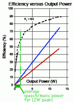
It happens my uncle just discovered "TriPath" (clone) and I plotted efficiency for A B and D. Attached. Assuming a 12W amp driven to the edge of clipping, the B has a real efficiency of 10% (not 78% as when driven FULL) and the D is some better. Working a 600W amp in a job that only needs 10W-20W puts B down like 2%! All the voltage headroom you are not using is still dissipated as heat to give you your small output. Yes, a HG class switch-rail design could cut this dramatically. Even within the parameters of your existing 600W amp. Add +/-20V rails to your +/-100V rails so it runs 99% of the time with just-enough rail voltage. Of course it is unlikely that you could modify any existing 600W B amp to HG mode without burning a heap of energy in blown Silicon.
Attachments
The real eco crime is the inefficiency of speakers, don't you think?...
Hi Brian
I have some of the most efficient speakers it is possible to buy, but then people say they are "over-provisioned"
Best wishes
David
...No hard answers...
Many issues to consider, true.
But now I have the speakers, I don't plan to buy new drivers just because my current ones could play a 500 seat cinema.
And I have a stock of Thermal Trak output transistors so silicon cost for a 20 W amp or a 300 W amp is similar, still need much the same front end.
Whereas the resale of an 18" JBL sub-woofer is way better with a 300 W matched amp than a 20 W unit.
Especially if it's a state of the art efficient 300 W
So it's down to the power supplies to determine the economics.
Also, as Brian appreciated, it's a fun problem too, I have some ideas that are new AFAIK.
Do you have any expertise in LLC or other ZVS/ZCS circuits?
Best wishes
David
Last edited:
Hi Brian
Also, as Brian appreciated, it's a fun problem too, I have some ideas that are new AFAIK.
Do you have any expertise in LLC or other ZVS/ZCS circuits?
Best wishes
David
In relative terms I do not know dick. However...
I was also thinking of a ZVCVSZS LCLLLCL differentially constrained single switch power factor corrected second side modulated all in one Zero Ripple direct transformer to load output Retro Encabulator with 99.9999% conversion efficiency.
AFAIK this is a new idea. Perhaps someone can provide me with a circuit diagram.
Some of the latest advances in MOSFET switching technology is in GaN. They are high power and high speed ideal for RF and microwave. Audio doesn’t really need ultrahigh speed, but since you asked about advances. They are interesting and certainly SOA.
https://epc-co.com/epc/Portals/0/epc/documents/product-training/Appnote_GaNfundamentals.pdf
https://epc-co.com/epc/Portals/0/epc/documents/product-training/Appnote_GaNfundamentals.pdf
Class D is all about switching speed. You really need a carrier frequency of about 400 kHz for full range operation. Just about any transistors can be made to switch at that frequency, but the faster they turn on and off the lower the switching losses. And the shorter the dead time between one turning off and the other turning on the lower the distortion.
The actual semiconducor physics of even old school silicon MOSFETs aren’t really the limiting factor in their speed. They switch very fast if you can pull the gate charge out fast enough. This is often limited by package inductance and the external circuit. The advantages of things like GaN is you can make a very small high current chip. This enables building an electrically “small” circuit with low capacitance and inductance per ampere of current capacity.
The actual semiconducor physics of even old school silicon MOSFETs aren’t really the limiting factor in their speed. They switch very fast if you can pull the gate charge out fast enough. This is often limited by package inductance and the external circuit. The advantages of things like GaN is you can make a very small high current chip. This enables building an electrically “small” circuit with low capacitance and inductance per ampere of current capacity.
In relative terms I do not know dick.
Ok, I was briefly mistaken.
Some of the latest advances...in GaN
Thank you for that link, when I didn't receive much response initially I started to look at GaN myself.
Some of the performance metrics are better than Si but, yes, I am not sure if they provide much benefit for audio.
It does look a reasonable option however, and would be fun, not to mention "latest SOTA transistors" claims.
...You really need a carrier frequency of about 400 kHz...And the shorter the dead time...the lower the distortion.
...an electrically “small” circuit with low capacitance and inductance per ampere of current capacity...
Yes, many trade-offs of efficiency, distortion, complexity and cost.
That's why the ZVS/ZCS circuitry interests me, better efficiency and lower EMI.
The electrically small circuit implies physically small too, so inevitably SMT.
I don't want to push that too far but it should please "Krisfr".
Best wishes
David
Last edited:
ZVS/ZCS switching is applicable to the power supply, but not the amplifier. The timing of the turn-off needs to be in sync with one of the resonant modes of the circuit. In a class D amp or tracking down converter, the position of the zero crossings is going to move around.
...the turn-off needs to be in sync with one of the resonant modes of the circuit...
A SMPS can vary the power to the load, which is all a down converter has to do.
The down converter doesn't have to be PWM at fixed frequency.
Apparently it's typical for an LLC circuit to maintain ZVC/ZVS over a 3 to 1 frequency variation.
The quiescent current draw of the linear amp actually helps to provide a load so the down converter doesn't have to vary too much.
So 900 kHz to 300 kHz perhaps, the ratio can be limited by choice of the inductance ratio for the two Ls in the LLC.
I suspect that a class-D could be done similarly but am less positive.
Best wishes
David
Last edited:
The down converter’s output voltage and will need to change directly one for one with the instantaneous output voltage of the amplifier, and the current change proportionally once the output current gets above the quiescent value. It’s a big swing - it needs to be in order to maintain efficiency (keeping Power lost to a few volts times Iout).
An LLC supply may stay in resonant mode over a 3:1 range of load current by changing the switching frequency, but it’s output voltage remains fairly constant. The tracker will swing over a lot more than 3:1 - and the current and voltage change together. I doubt even the guys that designed the Labgruppens have figured out how to keep soft switching over that much range. If you do you could make a lot of money...
An LLC supply may stay in resonant mode over a 3:1 range of load current by changing the switching frequency, but it’s output voltage remains fairly constant. The tracker will swing over a lot more than 3:1 - and the current and voltage change together. I doubt even the guys that designed the Labgruppens have figured out how to keep soft switching over that much range. If you do you could make a lot of money...
...over a lot more than 3:1
The 3:1 represents a reasonable frequency variation, this is not the same as the achievable load variation.
The trick is to have a wide load variation result in a small frequency variation.
The relationship between the two variations depends on the details of the converter and is not clear to me yet.
But it looks doable.
If you do you could make a lot of money...
I just wanted a nice system for my home!
Then I have ideas and it becomes a quest to satisfy my curiosity.
Best wishes
David
3:1 is about the range of load current that an LLC can stay in resonant mode (by adjusting frequency and duty cycle). At low currents it is not and the efficiency drops somewhat. But it’s still less heat than at full load where it operates at full efficiency. I wouldn’t sweat the fact that the converter will be a hard switched application - or at least it will over the majority of its operating range. It is still going to be way more efficient than a class B amplifier.
3:1...load current that an LLC can stay in resonant mode...
Do you have a reference for this?
Or an example, specifications for a typical LLC SMPS maybe?
Best wishes
David
I finally returned to this project and had a look at more recent developments.
I noticed that the Benchmark AHB2 amplifier uses this technique and achieves the best performance I have seen measured for any amplifier.
So it looks like the idea was more than reasonable.
The time lapse was also a chance to reexamine the idea with fresh eyes.
The reduced power dissipation means I can simplify the OPS, no need to parallel several OP transistors for power, only to keep current low to reduce beta droop.
So now FET OPs look better and I can reduce the quiescent current from my earlier estimates.
I have learned more since the last thread post but would still like to have some other people's inputs.
Is there more interest in the idea these days or are people still stuck on linear supplies and/or off-the-shelf SMPS?
David
- Home
- Amplifiers
- Power Supplies
- State of the Art for Tracker/Down Converter?