Hi there!
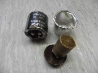
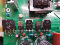
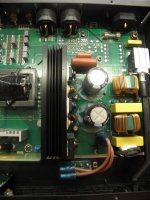
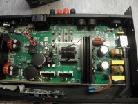
I have Adam Halls LD Systems XS400 (china?) amplifier. When it come to me it has blown psu as I find later because of dried primary bank elco. I have replaced all destroyed parts:
P1F should be Rohm PZT2222A
13005A replaced by MJE13007
(2S)C4138 replaced by J13009
For R10 and R16 im not 100% sure because of massive damage but I think it was 4R7
And of course, both primary bank elcos.
With all parts replaced amplifier worked normaly but after 14 days of use blew whan turned on. I replaced damaged parta again and trying multiple power cycles and eventually after some 20 it blew.
Do any of you have an idea what could be the problem with it?
Best regards
Attachments
Good work. In parallel I did a finding, the PSU circuit is copied from Yamaha YST-SW800. You can search and download the service manual.
This is a funny "Chinese special" controller-less SMPS circuit, copied from Yamaha "kamikaze" circuit.
- It has no current limiting at all.
- It has no softstart at all. Original implementation has a relay bypassing 6.8 ohm for softstart, with delay, fed from transformer winding.
- Original implementation has far bigger primary capacitors.
- In this implementation bigger primary capacitors will not work for reducing startup current in the transformer, at least not without revising inrush current limiter (ICL) NTC design. NTC resistance lowers nearly logarithmically as the element heats up, with bigger capacitors it heats faster. Maybe the trick was the scam of smaller capacitors.
- Original implementation has two 470uF output capacitors, instead of two 4700uF. Inrush current through the transformer is somewhat higher.
- Only the base of outer transistor of the HV darlington is driven close to optimally.
- At low load the outer transistor does most of the work.
- At high load (including startup) the inner transistor does most of the work.
- The inner transistor has no negative base bias to speed up turn off. It turns off slowly and lossy (good anywhere except in SMPS). A drastic increase in chip temperature is to be expected for each power up event, so if events are too close one of the inner transistors may blow (then a lot more parts). This may also depend on the conduction angle at which the power switch is turned on.
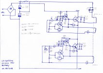
Please check component values against the original schematic, although it is clear that some parts are different, not necessarily better. The turn ratio of the auxiliary windings almost surely is different.
Did it blow at closely repeated power on and off?
Did you touch the trimmer?
Do you have a capacitance tester to check the small electrolytics?
Did you check all parts of the PSU?
Is the NTC OK?
Can you get an oscilloscope with storage function for analyzing startup? Maybe tweaking the circuit for more safety margin can do the trick.
EDIT: Incidentally, a few weeks ago I offered custom advanced amplification technology to the company that owns LD systems, they replied that my profile was interesting but they did not have "a position" for me. Maybe reliability is not about "positions"? Interestingly that's a company claiming German design haha
This is a funny "Chinese special" controller-less SMPS circuit, copied from Yamaha "kamikaze" circuit.
- It has no current limiting at all.
- It has no softstart at all. Original implementation has a relay bypassing 6.8 ohm for softstart, with delay, fed from transformer winding.
- Original implementation has far bigger primary capacitors.
- In this implementation bigger primary capacitors will not work for reducing startup current in the transformer, at least not without revising inrush current limiter (ICL) NTC design. NTC resistance lowers nearly logarithmically as the element heats up, with bigger capacitors it heats faster. Maybe the trick was the scam of smaller capacitors.
- Original implementation has two 470uF output capacitors, instead of two 4700uF. Inrush current through the transformer is somewhat higher.
- Only the base of outer transistor of the HV darlington is driven close to optimally.
- At low load the outer transistor does most of the work.
- At high load (including startup) the inner transistor does most of the work.
- The inner transistor has no negative base bias to speed up turn off. It turns off slowly and lossy (good anywhere except in SMPS). A drastic increase in chip temperature is to be expected for each power up event, so if events are too close one of the inner transistors may blow (then a lot more parts). This may also depend on the conduction angle at which the power switch is turned on.
Please check component values against the original schematic, although it is clear that some parts are different, not necessarily better. The turn ratio of the auxiliary windings almost surely is different.
Did it blow at closely repeated power on and off?
Did you touch the trimmer?
Do you have a capacitance tester to check the small electrolytics?
Did you check all parts of the PSU?
Is the NTC OK?
Can you get an oscilloscope with storage function for analyzing startup? Maybe tweaking the circuit for more safety margin can do the trick.
EDIT: Incidentally, a few weeks ago I offered custom advanced amplification technology to the company that owns LD systems, they replied that my profile was interesting but they did not have "a position" for me. Maybe reliability is not about "positions"? Interestingly that's a company claiming German design haha
Last edited:
EVA I think you have a point here with such a large capacitor bank on the secondary side. I have the same problem with a smaller version (sx200). it blew just like the one described here.
My remedy seeing all this will probably be a 20mm 5 ohm PTC in the center of the half bridge, this will limit inrush current on start up a lowering in value as load is pulled through it thus eliminating losses.
My remedy seeing all this will probably be a 20mm 5 ohm PTC in the center of the half bridge, this will limit inrush current on start up a lowering in value as load is pulled through it thus eliminating losses.
Hi Silvi,
Many thanks for your very useful post (and Eva too) on this amplifier. I am looking to repair an XS400 with the same problem - several parts blown in the PSU after just a couple of years of use. Did you have any final success with yours? If so, I am particularly interested to know if you continued with the replacement parts that you mentioned, or if you finally used any different types?
And also, if you added a 5 ohm 20mm NTC between the centre tap of the secondary and secondary ground as you suggested - if I have understood this correctly (you said PTC, but perhaps NTC was meant?) - or if you made any other improvements to the circuit? Also, if you found any need to adjust the trimmer (POT1), and how to do this?
Or, if anyone else also has any additional suggestions then I would be most grateful. Thank you.
..my solution on a LD-XS200 (same PCB, same broken Parts..)
renew both C7/C8 with 250V/680µf (up to 1000µF is possible, max. height is 32mm, dia. max. is 35mm)
renew both ST13005A (not MJE13005!!!)
renew both PZT2222A..
renew both C4138 (BU2527AW works fine..)
check/renew C10&C12 (100µF/16V)
check/renew C11&C14 (1nf/1kV)
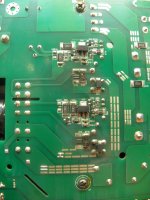
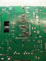
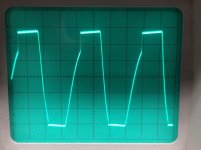
check symmetry as shown..(warning! an isolating Transformer is necessary!!! and use a 100W Bulb also.)..
renew both C7/C8 with 250V/680µf (up to 1000µF is possible, max. height is 32mm, dia. max. is 35mm)
renew both ST13005A (not MJE13005!!!)
renew both PZT2222A..
renew both C4138 (BU2527AW works fine..)
check/renew C10&C12 (100µF/16V)
check/renew C11&C14 (1nf/1kV)
check symmetry as shown..(warning! an isolating Transformer is necessary!!! and use a 100W Bulb also.)..
Attachments
Last edited:
Having fixed several of these amplifiers till now the main culprits are the two 100uF /16v capacitors C10 and C12. When these tend to lower their capacitance with age or as they start to dry up the oscillating frequency which should be around 20Khz starts dropping until with too low a frequency the transformer will saturate and the transistors blow.
Remedy, I fit a 100uF/ 50v rating cap instead of 16v I also use a good quality one here with low ESR. When frequency starts dropping all sorts of faults happen even the IRS2092 will lock on protection for no reason. Just changing these two capacitors cured this problem. Believe me I spent hours trying to find whats wrong on the amplifier side and at last finding the smps oscillating at around 12khz. I change those capacitors and the fault on the amplifier disappeared.
Remedy, I fit a 100uF/ 50v rating cap instead of 16v I also use a good quality one here with low ESR. When frequency starts dropping all sorts of faults happen even the IRS2092 will lock on protection for no reason. Just changing these two capacitors cured this problem. Believe me I spent hours trying to find whats wrong on the amplifier side and at last finding the smps oscillating at around 12khz. I change those capacitors and the fault on the amplifier disappeared.
- Status
- This old topic is closed. If you want to reopen this topic, contact a moderator using the "Report Post" button.
- Home
- Amplifiers
- Power Supplies
- LD Systems XS400 PSU