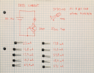
Back to J113. I run some drain current tests with various resistors and various voltages today. Results suggest:
For 5-10mA IDSS (less likely to find in current production J113) keep the same 270 Ohm R4 R7 R8 value. For 10-20mA IDSS use 560 Ohm R4 R7 R8. For >20mA IDSS use 750 Ohm R4 R7 R8.
When having few samples from different IDSS ranges, use the appropriate resistor value to each sample's position. J1 corresponds to R4, J2 to R7, J3 to R8. Prefer the lowest IDSS samples for J3 when its for 5V rail set regs.
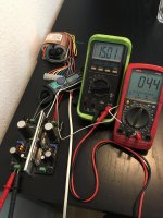
Sorting J113s for IDSS takes a semiconductors tester or to put them on a breadboard and connect G+S pins together. Use +15V with a milliamper meter between +V and D (drain) pin in series. 0V to S pin. That is the datasheet's test voltage. Using a 9V battery will give bit less IDSS but still indicative.
Test the samples replacing one by one in the rig. Measure carefully to avoid accidental shorts that can break the mA measuring DMM's fuse. Note their results on paper. Place each sample next to its mA note.
Because J113 is 35V rated don't use higher than 28VAC transformer. Thus the Ubib's suggested max output shortens to 33VDC for good enough Vin-Vout margin when using this JFET type.
Although PF5102 and J113 are brothers, in general I prefer the PF5102 due to its lower more predictable IDSS range and 5V higher official spec. Seems like that type is a subset of J113 production with more controlled characteristics. While coming from the same chopper JFETs family it is alternatively described as low frequency low noise amplifier in the manufacturer's website.
P.S. I will refer this information in post #1 also
Mahalo nui loa
Thank you very much
Ultrbib running with J113 JFET
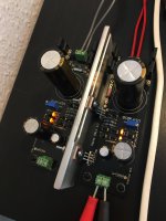
UltraBib is running fine with the J113 JFET instead of the PR5102.
I measured the IDSS current as Salas recommended in post #1559 and changed the corresponding resistors. I only had two 560 Ohm, so they went in for the highest mA rated J113. I used 510 Ohm for the rest. I hope it is fine...")
I have attached a picture of my measuring results. They can properly not be used as "scientific" results with only 10 pcs, but maybe used for any further development to others.
The Heat sink is definitely to small for two Ultrabibs in this setup. The area/size must be larged. I have set the ccmA at 180 mA (3.3 Ohm)...
Next is to build this into my DAC. Thanks for your help Salas
UltraBib is running fine with the J113 JFET instead of the PR5102.
I measured the IDSS current as Salas recommended in post #1559 and changed the corresponding resistors. I only had two 560 Ohm, so they went in for the highest mA rated J113. I used 510 Ohm for the rest. I hope it is fine...
I have attached a picture of my measuring results. They can properly not be used as "scientific" results with only 10 pcs, but maybe used for any further development to others.
The Heat sink is definitely to small for two Ultrabibs in this setup. The area/size must be larged. I have set the ccmA at 180 mA (3.3 Ohm)...
Next is to build this into my DAC. Thanks for your help Salas
Attachments
Last edited:
You are welcome. Those J113 samples are behaving as expected. In other words their modern production is hot for IDSS average.
To confirm what bias current they run in circuit for each position you can measure the voltage drop across each one's source resistor and divide by its Ohmic value.
To confirm what bias current they run in circuit for each position you can measure the voltage drop across each one's source resistor and divide by its Ohmic value.
Ubib PSU
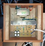
Did my first built of Ubib at 800mA 9V PSU for a digital player to replace the small outboard adapter that came with it.
It sounded cleaner and more transparent with very good bass extension so far.
The original adapter is rated 1.5A. I have not noted any problem with the Ubib so far at 0.8A with music that I played including some very dynamic ones.
Attachments
I solved the problem of my case:
Problem:
2 UltraBiB Regs(@+/-15V) output normal +/-15V without load.
Once connected to amp, there is voltage drop on both V rails or one side is 15V, the other is 0V. LED are not bright.
cause:
The Regs' 4 FETs are shorted somewhere when screwed down to the aluminium chassis.
(metal screws+plastic rings and mica insulator sheets TO-220 size)
Remedy:
Use of plastic screws+plastic rings and bigger insulator sheets.
I also removed all heat dissipating paste (I know there is a conductive type but not sure what type I used)
It is a stupid mistake as usual.
Hope this would help others when they troubleshoot.
The regs have excellent protection circuitry by the way.
PS:
It sounds wonderful - more airy, more dynamic, more everything.
Thank you very much Salas!
I solved the problem of my case:
Problem:
2 UltraBiB Regs(@+/-15V) output normal +/-15V without load.
Once connected to amp, there is voltage drop on both V rails or one side is 15V, the other is 0V. LED are not bright.
cause:
The Regs' 4 FETs are shorted somewhere when screwed down to the aluminium chassis.
(metal screws+plastic rings and mica insulator sheets TO-220 size)
Remedy:
Use of plastic screws+plastic rings and bigger insulator sheets.
I also removed all heat dissipating paste (I know there is a conductive type but not sure what type I used)
It is a stupid mistake as usual.
Hope this would help others when they troubleshoot.
The regs have excellent protection circuitry by the way.
PS:
It sounds wonderful - more airy, more dynamic, more everything.
Thank you very much Salas!
The voltage drops when the load is on, which means that a component is burned. You need to check each component one by one. The most easily burned component is a transistor.
Right now the whammy sounds excellent with UltraBiB.
I want to enjoy the music for the next couple days before going back to check everything.
I got the Quasimodo test done successfully and populated that section on UltraBiB.
Theoretically it should be better but I did not do any comparison as the v drop caused enough frustration.
Thank you everyone for the help. I appreciated it very much.
Or it was a partial short allowing few spare mA for the shunt voltage section to appear working well before loaded
I once mistakenly inserted the 3.3V Regulators into the 1.2V position on the Buffalo and plugged the 1.3V Regulators into the 3.3V position on the Buffalo. As a result, the 5V power supply drops to 1V.
 Fortunately, Buffalo has a protective design, otherwise Buffalo has been damaged.
I would try powering a class A amp using Ultrabib, the project is a high voltage version of ACA Pass amplifier. Now I must order the transformers. Each ACA-channel needs approx. 24VDC input voltage rated at 1,6A.
I think is a must double mono tr. as in DCB3 preamp but a greater 100w. core or maybe more 120w core??.
No idea what voltage for Ultrabib to produce 24v. DC.
As rectifier I will use an active bridge based on LT4320, which is a "low-drop" rectifier.
I think is a must double mono tr. as in DCB3 preamp but a greater 100w. core or maybe more 120w core??.
No idea what voltage for Ultrabib to produce 24v. DC.
As rectifier I will use an active bridge based on LT4320, which is a "low-drop" rectifier.
Depends not only on bridge losses but also on how much ripple voltage loss is going to be created. 24VAC trafos and 10mF C1 or higher would be a safer bet. M1 should be IRF9630 since you must run high Amperage CC. 120VA is a good choice as well. Fuse the primary side as indicated by the transformers manufacturer.
Finished converting a balanced Soekris 1121-based DAC powered by multiple DIYINHK LT3045 power supplies to power via three UBiBS a few weeks ago.
From the beginning there was a noticeable improvement in sound quality overall - especially top to bottom resolution and soundstage width. Lyric intelligibility is also improved. After several weeks I’m still smiling hours after sitting down to listen so felt I should give credit where it’s due.
And, to (mis)quote someone ‘... you should let people know that SOTA LDOs can be bettered by UBiBs’. They certainly improved that DAC. Thanks, Salas, for a benchmark power supply.

In your case for say 1.75A CC you should use 0.33R R1*. It will dissipate 1W so use a 3W-5W resistor. Rule of thumb is choose at least three times higher nominal than their dissipation for passive parts. Not to become truly hot i.e. untouchable and dangerous.
*You know the formula, its CC=Vbe/R1. In this circuit no more than 0.6V/R1, usually 0.58V Vbe in average after warmed up as reported by the builders. 0.58V*1.75A=1W R1 dissipation.
*You know the formula, its CC=Vbe/R1. In this circuit no more than 0.6V/R1, usually 0.58V Vbe in average after warmed up as reported by the builders. 0.58V*1.75A=1W R1 dissipation.
- Home
- Amplifiers
- Power Supplies
- Salas SSLV1.3 UltraBiB shunt regulator