greetings
i own a device rated for 22VDC x 1100mA powersupply
the original switching P/S is unacceptable because it's very noisy and doesn't have grounding
i've purchased a linear transformer with grounded core, isolated layers and magnetic shielding
the output of this transformer is 22VAC x 1400mA
i need to rectify the AC signal, then drop it back to 22V, filter the pulses and make the voltage very stable and silent/noiseless
the most important thing for me in this project is SIMPLICITY and using the least parts possible
could someone please help me design it?
Can I suggest starting with the simplest design (diode bridge, filter capacitor, dropping resistor) to power your load. From that you can then elaborate on what aspects may, or may not, be providing the required performance required from your powered equipment.
At the moment you haven't identified any actual performance requirements, other than descriptive adjectives. Also you haven't really clarified how the original smps is not meeting a certain level of performance ('very noisy' doesn't really clarify levels or characteristic or impact on application).
If you are not sure on the basic design and operation of the suggested linear power supply, then the simulation program PSUD2 would be my recommendation for progressing what diodes and filter cap size and dropping resistor may suit your load.
LM317 data sheet.the most important thing for me in this project is SIMPLICITY and using the least parts
There could be another problem... at least we need this clarifying.
Does the intended application really draw 1.1 amp ?
A 1.4 amp secondary will be underrated supplying a continuous rectified and smoothed DC current of 1.1 amp.
i own a device rated for 22VDC x 1100mA powersupply
Does the intended application really draw 1.1 amp ?
the output of this transformer is 22VAC x 1400mA
A 1.4 amp secondary will be underrated supplying a continuous rectified and smoothed DC current of 1.1 amp.
First question.
Has the transformer a single 22 volt AC winding, or is it a dual type of 0-22, 0-22, or is it a tapped 22-0-22 type.
And welcome to diyAudio")
thanks Mooly
the transformer output is a 2-wire single 22v AC winding (just the 0v and the 22v)
Can I suggest starting with the simplest design (diode bridge, filter capacitor, dropping resistor) to power your load. From that you can then elaborate on what aspects may, or may not, be providing the required performance required from your powered equipment.
At the moment you haven't identified any actual performance requirements, other than descriptive adjectives. Also you haven't really clarified how the original smps is not meeting a certain level of performance ('very noisy' doesn't really clarify levels or characteristic or impact on application).
If you are not sure on the basic design and operation of the suggested linear power supply, then the simulation program PSUD2 would be my recommendation for progressing what diodes and filter cap size and dropping resistor may suit your load.
it's for a tube distortion pedal, for electric guitar, the pedal is a Blackstar HT-Dual, 2012 version, rated for 22VDC x 1100mA
the SPS came stock with the pedal, the sps model is labeled as: KSAS0242200109M2, made in china
one of the main sources of the noise is grounding related since the hum attenuates when i touch the pedal chassis, the sps isn't grounded at all, and i realized the sps noise and hum add microphonics to the tube too
There could be another problem... at least we need this clarifying.
Does the intended application really draw 1.1 amp ?
A 1.4 amp secondary will be underrated supplying a continuous rectified and smoothed DC current of 1.1 amp.
it says so on the device label, then i guess it draws 1.1a
Hmmm... guitar pedals are outside my experience although they normally draw small current but these Blackstar HT-Dual that I can see appear to be valve based.
Do you have link or picture to the pedal. If it is valve operated then it could well be that it really does draw the current they say.
Do you have link or picture to the pedal. If it is valve operated then it could well be that it really does draw the current they say.
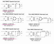
I found this for you. It explains the relationship between transformer current (the AC rating) and the DC current you can draw after rectifying the voltage.
You would be using "FULLWAVE BRIDGE Capacitor Input Load" as they call it. The raw DC voltage would be around 30 volts DC which you would then drop down with a suitable regulator.
If you are able to access the 22 volt feed (perhaps in the pedal) and could insert an ammeter then you could measure the current draw. 1.1 Amps would need to read on a high amps range on a suitable meter.
Attachments
Hmmm... guitar pedals are outside my experience although they normally draw small current but these Blackstar HT-Dual that I can see appear to be valve based.
Do you have link or picture to the pedal. If it is valve operated then it could well be that it really does draw the current they say.
Blackstar HT Dual Valve Guitar Pedal
| Blackstar Amplification
older versions had 16v PS and some had AC PS!!
mine is earliest with 22vdc x 1100mA
I found this for you. It explains the relationship between transformer current (the AC rating) and the DC current you can draw after rectifying the voltage.
You would be using "FULLWAVE BRIDGE Capacitor Input Load" as they call it. The raw DC voltage would be around 30 volts DC which you would then drop down with a suitable regulator.
If you are able to access the 22 volt feed (perhaps in the pedal) and could insert an ammeter then you could measure the current draw. 1.1 Amps would need to read on a high amps range on a suitable meter.
thanks! (it really draws 1.1a)
Thanks
Right then ... so it is a valve job.
So the next step has to be to confirm what the real current draw is. If you look at the pdf above it gives the relationship between transformer current and the DC current that can be drawn which is around '0.6' meaning that a 1.4A transformer would supply around 0.85 A DC.
Another thought... the pedal must include its own switching supply to step up the 22 volts to the 300 volt HT mentioned. That could also be a source of noise
I'll have to leave it for tonight but hopefully the above will give you something to work on.
thanks! (it really draws 1.1a)
Just because the label says that, it doesn't automatically mean it actually does. It could be close or a little lower than we think.
The HP mouse I use says 40ma @ 3 volts and yet batteries last for 6 months...
Blackstar HT Dual Valve Guitar Pedal
| Blackstar Amplification
older versions had 16v PS and some had AC PS!!
mine is earliest with 22vdc x 1100mA
Since most tubes require much more voltage than 16 or 22, does it have an internal switcher that generates high voltage? That would also explain the 1.1A draw.
Edit: I see Mooly has made the same point.
Jan
Since most tubes require much more voltage than 16 or 22, does it have an internal switcher that generates high voltage? That would also explain the 1.1A draw.
Edit: I see Mooly has made the same point.
Jan
yes, internally the pedal converts the 22vdc into a higher voltage
it's for a tube distortion pedal, for electric guitar, the pedal is a Blackstar HT-Dual, 2012 version, rated for 22VDC x 1100mA
the SPS came stock with the pedal, the sps model is labeled as: KSAS0242200109M2, made in china
one of the main sources of the noise is grounding related since the hum attenuates when i touch the pedal chassis, the sps isn't grounded at all, and i realized the sps noise and hum add microphonics to the tube too
It is likely that all or most of the 'noise' is related to the AC grounding of your guitar rig - and is somewhat similar to a hi-fi system that experiences noise/hum when it connects to a major un-grounded (ie. double-insulated) smps device like a TV.
That form of noise can be alleviated by connecting all your rig power supplies (ie. amp and power supplies for other pedals) to one AC power 'board', but is likely to need a ground 'lift' circuit added to your guitar amp (such as a diode bridge with bypass caps).
The alternate path you are wanting to take, with a different type of grounded power supply, may achieve what you desire - but the requirement from such a new power supply is likely not an 'output voltage noise' performance level, but rather a system protective earth (ground) noise issue.
BINGO! you nailed it... thats right, i need to build a new power supply because the stock is non grounded and the power supplies that fit the draw requirements are pwm/noisy ones
so i purchased a transformer with grounded core, isolated layers and electromagnetic shielding in order to build this grounded supply in the most SIMPLE design possible
as i said the transformer maximum draw is 1400mA and have 2 wirings as dedicated output 22vAC (0/22)
can you please help me build it? it seems all i need is to know which diodes i use to rectify and then put some resistors to drop back the voltage to 22vDC and then filter the pulses with 2200uf caps
On the Hammond site.I found this for you.
Design Guide For Rectifier Use.pdf
That sheet has real problems. Note particularly the Capacitor Input Load conditions show different Peak and Average values. We use a capacitor to make average stay "near" peak. We need to know the R-C values to know how the average fall shy of the peak.
I asked Hammond to explain. They kindly told me they got it somewhere on the web, were not responsible for its content, do not give design advice, and suggest professional design help.
For more fun: Hammond specs a CT winding as the full voltage end-to-end (the way they sell them) but many newer plans will say 22V+22V or 22V-0-22V. So some numbers are half/twice what you expect.
For my self-pleasure(?), I marked-up the sheet for the circuits I know and care about.
Attachments
- Status
- This old topic is closed. If you want to reopen this topic, contact a moderator using the "Report Post" button.
- Home
- Amplifiers
- Power Supplies
- Help me design a Noiseless Linear P/S