You keep trying to make this point, but in reality this is a typical and superior design because it allows you to avoid a ground loop. Are you completely oblivious to the $$$ pedalboard power supplies where each individual supply is completely isolated?
they dont go for 22v / 1100mA
closest dc brick goes for 18v 780mA
Actually it probably is a high grade one, double-insulated, not needing a ground meaning you will have no ground loop issues.
Edit: I see leadbelly made the same point.
Jan
when i touch the pedal chassi the hum attenuates and when I asked someone else to ground it with its body the microphonics also attenuated, theres also other users of this device that related the same symptoms, did you and the other guy who claimed the same issue take a look at the PSU model i've described to back up this assumption, because i've never saw tube devices work well without ground dumping and the raw wall AC current comes contaminated with bad harmonics and other types of signal impregnated in the wave that needs to be filtered and dumped somewhere.
if the stock switching psu that came groundless is so good and capable of filtering the noise, cycle hum, bad harmonics and other types of current pollution, then where does it gets dumped? magic/teleportation or some fancy crap that doesnt exist for humans living in the face of earth?
^it may seem like sarcasm but consider it a serious question because who reply me might be a great tech/engineer and i'm trying to understand the point that was subjected instead of simply helping me to rectify an AC source and mantain it stable in the most simple way
thanks
Ground dumping? Try an adult diaper or Imodium.
What you really need to consider as a possibility is that you have completely misdiagnosed the cause of your hum problem, and back up and just describe the symptoms of the problem and ask for help.
my mother tongue is not english and some sentences might give the opportunity for lame flamers like you to come and exploit possible puns;
this lack of consideration from people like you is the proof that you and your kind are misqualified to be professionals since all you can do is this kind of ****** pricks instead of showing the best of your capabilities and effectively solve the simple puzzles that my topic has brought into discussion
if you cannot help with your electronic knowledge please refrain yourself because if you had any humouristic skills you'd have a different behaviour and i need not to describe the lack of character in what you are putting into this topic because i know you are no longer a children and got the picture i am drawing with my words;
i need not a teaser/flamer here. go somewhere else if you seek appreciation being a douche
what i need here is solution to what is been put into discussion: the project of a noiseless PS with grounding, using a linear transformer with 1400ma max current and 2 wires in the output (0-22vDC)
i contacted the manufacturer of this high end traffo that i'll use in this project and he guaranteed it have no current loss or dissipation, so its suited for this build
P, I suggest you try and appreciate the problem you face better, before you naively dismiss posts and preach solutions, as you are a newb to noise and grounding problems.
For those that are interested, I recommend reading chapters 1 and 2 in http://web.mit.edu/jhawk/tmp/p/EST016_Ground_Loops_handout.pdf, and replacing the power transformer in section 1.3, 2.3 etc with a smps that also has a variety of stray capacitances that couple to the secondary (ie. signal) side. Bill introduces some ground isolators and ways to break the ground loop path.
Any 'solution' is specific to the situation at hand, and of course could be achieved by a variety of techniques/equipments, and include swapping out a plugpack power supply with an alternative.
I'm going to use a diode ground lift/breaker in a diy stereo vintage hi-fi amplifier in a friends place that connects to a modern TV when I get a chance. There are many forum posts, and a few articles on that particular solution, such as Rod Elliot's webpage Earthing (Grounding) Your Hi-Fi - Tricks and Techniques
Last edited:
i contacted the manufacturer of this high end traffo that i'll use in this project and he guaranteed it have no current loss or dissipation, so its suited for this build
Here is another page giving information on transformer current relationships.
RECTIFIER TRANSFORMER CALCULATION
Jan clearly has more patience than me with people who insult him.Psicopanque said:you say it because you wanted to criticise me since i am being kind to everyone except smartasses that come in the forum with useless flabble in order to tease and flame the newcomers
my mother tongue is not english and some sentences might give the opportunity for lame flamers like you to come and exploit possible puns;
this lack of consideration from people like you is the proof that you and your kind are misqualified to be professionals since all you can do is this kind of ****** pricks instead of showing the best of your capabilities and effectively solve the simple puzzles that my topic has brought into discussion
if you cannot help with your electronic knowledge please refrain yourself because if you had any humouristic skills you'd have a different behaviour and i need not to describe the lack of character in what you are putting into this topic because i know you are no longer a children and got the picture i am drawing with my words;
i need not a teaser/flamer here. go somewhere else if you seek appreciation being a douche
what i need here is solution to what is been put into discussion: the project of a noiseless PS with grounding, using a linear transformer with 1400ma max current and 2 wires in the output (0-22vDC)
i contacted the manufacturer of this high end traffo that i'll use in this project and he guaranteed it have no current loss or dissipation, so its suited for this build
I need more popcorn. This is going to be a great show!
Jan
lol
P, I suggest you try and appreciate the problem you face better, before you naively dismiss posts and preach solutions, as you are a newb to noise and grounding problems.
For those that are interested, I recommend reading chapters 1 and 2 in http://web.mit.edu/jhawk/tmp/p/EST016_Ground_Loops_handout.pdf, and replacing the power transformer in section 1.3, 2.3 etc with a smps that also has a variety of stray capacitances that couple to the secondary (ie. signal) side. Bill introduces some ground isolators and ways to break the ground loop path.
Any 'solution' is specific to the situation at hand, and of course could be achieved by a variety of techniques/equipments, and include swapping out a plugpack power supply with an alternative.
I'm going to use a diode ground lift/breaker in a diy stereo vintage hi-fi amplifier in a friends place that connects to a modern TV when I get a chance. There are many forum posts, and a few articles on that particular solution, such as Rod Elliot's webpage Earthing (Grounding) Your Hi-Fi - Tricks and Techniques
thanks
Here is another page giving information on transformer current relationships.
RECTIFIER TRANSFORMER CALCULATION
thanks, i think theres losses too, but if the manufacturer said so i'll consider the specs he said and if it damages my equipment i'll sue him, lol
although the link you posted is great and i'll study it, real thanks
Jan clearly has more patience than me with people who insult him.
some people's patience can be raised and fortified like a well architected construction, others are drawn out like water stored in a recipient
mine patience seems to behave like yours, but i understand that i must shift from example B to example A to acheive a state of existance plenty of happiness
now its time to work hard on all the stuff, i found useful the lm 317 schem that our patient friend has put into consideration and i would add if it could be of greater results if i use instead a lm350 full metal can with mica spacers and poly screw supporters to regulate the tension in a less noise possibility
thanks
The LM350 is a 3 amp device and would be suitable. You do realise that any linear regulator will need a pretty large heatsink.
For example, a DC voltage input of 30 volts and a regulator output of 22 volts means that 8 volts is dropped across the regulator. Multiply that be the current (1.1A) and you get 8.8 watts.
That is more than you might think and a fairly substantial heatsink is needed.
Pretty sure it is the LM350K that is in the round T03 package although the 3 legged T0220 package can be easier to use.
The LM317 TO-220 is more than adequate for your current needs. A metal tab version should give 5C/W (junction to case tab) then add your insulator thermal resistance to your heatsink. So 8W will make the junction some 40C above the tab temperature. As said already, you need a reasonably large heatsink to keep the tab cool.
thanks guys, its gonna fit
i hope this topic might help as many as it helped me
special thanks to Mooly, but seriously, everyone that participated deserves a congratulation
big hugs to every1 and i hope someday i get able to support the newbies like you guys helped me resolve this situation
thanks
guilherme alexandre eugenio from brasil (hell)
Good luck with the project
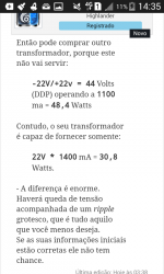
some guy on brazilian forums quoted that my 0-22vAC x 1400mA wouldn't fit the project because if i need is 22vDC symmetric it would be 44v and 48watts, and he claimed that my transformer would go up to 30watts and it could generate tension drop, ripple effect and other problems
is it truth?
Attachments
You have said right from the beginning that your requirement is for a single 22 volt DC supply of 1.1 amp capability. That means the original power supply has just two wires feeding the pedal.
A dual or split supply is totally different as it has two output voltages, one positive and one negative. The same rules apply to calculating voltages and current though.
You haven't got a dual supply though, and you also haven't got a dual or split winding transformer") Just a single winding.
Just a single winding.
Your transformer is rated at 22 volts AC and can deliver 1.4 amps into a resistive load. That means your transformer is a 30VA rated unit. We normally use the term VA or 'volt-amps' and not watts when dealing with transformer specifications.
Once you rectify and smooth that AC voltage then it can not supply (as we have mentioned) the same 1.4 amps into a resistive load, it must be derated (multiplied by) by that factor of 0.61 which gives just 0.85 amps.
A dual or split supply is totally different as it has two output voltages, one positive and one negative. The same rules apply to calculating voltages and current though.
You haven't got a dual supply though, and you also haven't got a dual or split winding transformer
Just a single winding.Your transformer is rated at 22 volts AC and can deliver 1.4 amps into a resistive load. That means your transformer is a 30VA rated unit. We normally use the term VA or 'volt-amps' and not watts when dealing with transformer specifications.
Once you rectify and smooth that AC voltage then it can not supply (as we have mentioned) the same 1.4 amps into a resistive load, it must be derated (multiplied by) by that factor of 0.61 which gives just 0.85 amps.
- Status
- This old topic is closed. If you want to reopen this topic, contact a moderator using the "Report Post" button.
- Home
- Amplifiers
- Power Supplies
- Help me design a Noiseless Linear P/S