And if I may ask the experts bit of a novice question, why would the designers have a 12V dc supply comming from a19V ac line?
The supply has to be derived from somewhere, and ultimately whether a standard mains transformer is used or an SMPS the basic raw voltage provided is always AC.
Yes, the higher DC voltage is a downside if a linear regulator is used because it is wasteful of power.
I wouldn't like to second guess why it has been done this way. Perhaps that AC winding is used for other things that need the higher voltage, and the cost of providing another lower voltage winding would have been to expensive.
I wouldn't like to second guess why it has been done this way. Perhaps that AC winding is used for other things that need the higher voltage, and the cost of providing another lower voltage winding would have been to expensive.
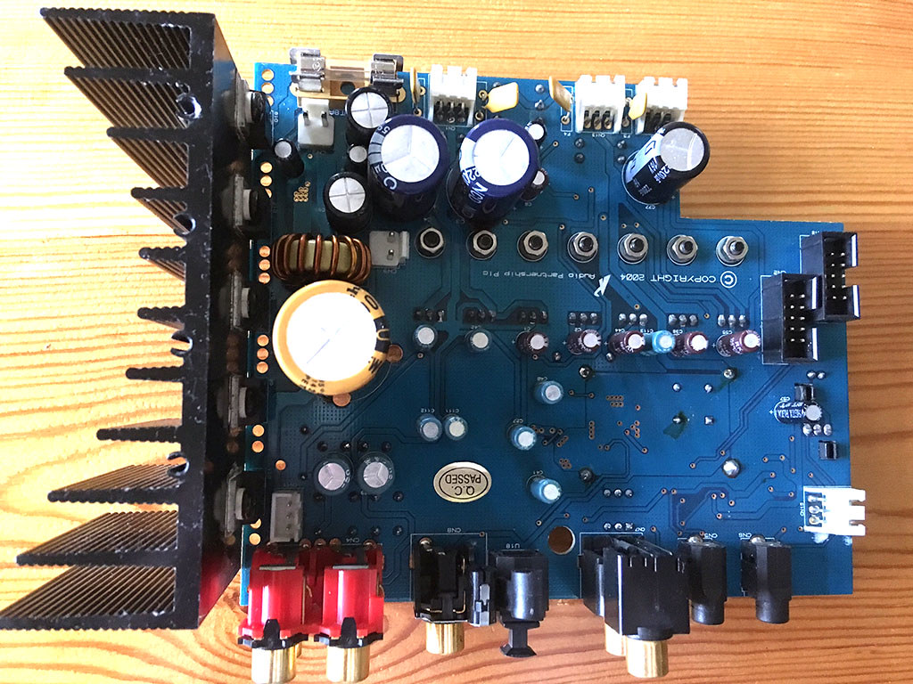
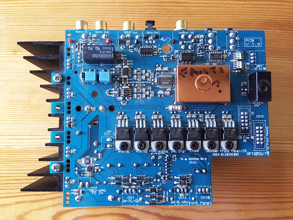
Hi, someone asked for photos of the DAC board...
 IMG_4027red by Alchad, on Flickr
 IMG_4026red by Alchad, on Flickr
IMG_4027red by Alchad, on Flickr
IMG_4026red by Alchad, on Flickr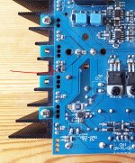
The coil with thick wire and the medium size capacitor near it are the LC output filter of a buck (step-down) switching regulator, current-mode type (R37 is the shunt that measures output current), conrolled by U1x SMD IC near R37. The power stage for this buck regulator is M50 (N-channel 30V FET) and one of the dual schottky MBRxxx diodes attached to heatsink.
The buck regulator converts about 26V DC (rectified from toroid) into 12V with high efficiency. That buck regulator will start to malfunction at high load as the input or output capacitor dry. This will happen faster in units subject to more heat and where the computer section has been given more intensive use.
Personally I think this is one of the 1st attempts of Cambridge Audio at doing a switching regulator... So typical failures to expect. It is a bad idea to power a computer from a mains frequency toroid transformer, this idea was dumped in 1980s by all computer manufacturers, stress is high, not like in audio amplifiers.
Remove both capacitors (the big one, and the one near the step-down 12V output coil) and check capacitance and ESR. Find out about the brand and series of capacitors used, ESR and ripple current data, and replace by something with similar specs if degraded.
Alternatively just swap these 2 capacitors (be careful soldering) between working and faulty unit and I bet the fault will move with the capacitors. The faulty unit, due to different working conditions (more capacitor aging), may need re-capping (checking all capacitors and replacing the ones over 10~20% out of spec).
Note that capacitors in power supply can dry as a chain reaction when capacitors in motherboard dry, and these things are probably from "badcaps" era. This is not a reason for dumping electronics from that era, one of my computers is a P4 motherboard that has been recapped twice (last time it blew CPU voltage regulator IC as caps dried, but I had a spare from another board and I added protection for next time), fed by a ATX supply that also has been recapped twice, over 10 years working 24/7, last re-capping was done with Aluminum-Polymer electrolytics in many locations, which exhibit lower ESR, higher ripple current, and longer life (lower ESR might be a problem in critical locations such as LC output filter of CPU voltage regulator, this needs consideration, to match original ESR, as new caps will have lower ESR to uF ratio).
Eva,
Thank you for taking the time to post such a comprehensive reply.
My knowledge of electronics (nor I think my simple multimeter!) is not sufficent to check out the capacitors, but I have actually replaced the large capacitor and the smaller one to the top right of the photo (the larger one because I figured it had to have something to do with the problem being near the action part of the circuit!, and the smaller one because it appeared to be bulging slightly. I did order replacement caps for the medium two and will replace them as you suggest.
One two part question if I may - you say "the buck regulator converts about 26V DC (rectified from toroid)".
From the checks I have done I believe the voltage from the torroid is AC - would that be correct, and if it is AC where/what is actually doing the conversion to DC - is this what you mean by rectification.
Sorry if it's a stupid question, and once again thanks for replying.
Regards
Have you checked that joint in the photo ? The joint right at the top of that picture is also bad enough to show up in a photo, the solder is cracked all around the pin.
Those are all classic old fashioned faults.
Yes, double checked with a magnifying glass and all look OK. Would it be OK to make double sure by putting a soldering iron on each?
How can you order replacement capacitors if you can't test a capacitor (buy a cheap multimeter with cap tester, learn to test higher value caps placing another cap in series) and don't know what AC rectification is? Not all capacitors are suitable for that duty (premature fail).
EDIT: If you fear swapping capacitors from a board to another in such a simple design your relationship with electronics is irrational, and such relationships only serve one purpose, and it is not repairing anything (more likely ejecting safety capsule and destroying main ship).
EDIT: If you fear swapping capacitors from a board to another in such a simple design your relationship with electronics is irrational, and such relationships only serve one purpose, and it is not repairing anything (more likely ejecting safety capsule and destroying main ship).
Last edited:
How can you order replacement capacitors if you can't test a capacitor (buy a cheap multimeter with cap tester, learn to test higher value caps placing another cap in series) and don't know what AC rectification is? Not all capacitors are suitable for that duty (premature fail).
EDIT: If you fear swapping capacitors from a board to another in such a simple design your relationship with electronics is irrational, and such relationships only serve one purpose, and it is not repairing anything (more likely ejecting safety capsule and destroying main ship).
Ordering replacement caps - as I've said before, my knowledge of electrical technology is absolutely minimal - I ordered replacements by using the data on the old caps and buying what seemed to be decent quality ones - they were not expensive.
However, I've no intention of swapping caps between the good board and the bad. That is not irational, to me it's common sense, although I've done an lot of soldering etc in the past it's been on central heating system, not small intricate stuff such as on a circuit board. If I mess things up I could well end up with 2 faulty boards. As I've also said before, I bought the faulty music server to play with and have a bit of fun trying to repair it.
As for "simple design" - maybe it is if playing with them is your hobby or profession, to me it's more than complicated enough.
Once again, thanks for the reply.
Yes, double checked with a magnifying glass and all look OK. Would it be OK to make double sure by putting a soldering iron on each?
It is definitely OK to resolder all those. If the joint is already poor then you may find the solder doesn't 'take' well to the pins. If so then clean them up with a little emery paper.
What is the black I am seeing in that picture ? It looks like carbonisation from arcing at the joint.
I know photos are open to interpretation but if that is a shot of your actual board then I would say those joints are defective.
Look at the last couple of pictures in post #1 here:
Sony CDP790 and KSS240 Restoration Project
This is what I am seeing in yours. The solder looks cracked around the pins. Its a classic failure mode that is industry wide.
Sony CDP790 and KSS240 Restoration Project
This is what I am seeing in yours. The solder looks cracked around the pins. Its a classic failure mode that is industry wide.
What is the black I am seeing in that picture ? It looks like carbonisation from arcing at the joint.
I know photos are open to interpretation but if that is a shot of your actual board then I would say those joints are defective.
George Washington moment - "I cannot tell a lie" - I did arc a couple of times when I was using the multimeter to try and check those devices - probes touched each other a couple of times.
") Lol and worse
Lol and worse - Status
- This old topic is closed. If you want to reopen this topic, contact a moderator using the "Report Post" button.
- Home
- Amplifiers
- Power Supplies
- Why only half voltage?