Hi,
I know my way around the inside of a computer, but am completely unfamiliar with anything using capacitors and resistors etc
By way of explanation before I get to my question, I have an old Cambridge Azur 640H music server - basically a mini PC with supposedly high end hifi bits inside. It stores music on a hard drive. I've had it for quite a few years and have undertaken various repairs/replacements and have grown quite attached to it, and very familiar with it's internals.
Anyway another one came up for sale on Ebay as "spares or repairs" and fancying a challenge I bought it. Swapping bits between the good unit and the Ebay one, I've narrowed the problem down to what I think is the DAC (?) unit which appears to transfer a 12 volt supply from the mains transformer to the motherboard. I can measure the voltage from the DAC unit to the motherboard and for the good unit it is 12 volts and for the Ebay one it is only 6 volts (this is with the DAC unit being fed from the same mains transformer) from the good unit.
I’ve tried to attach 2 photos which show the kit in question.
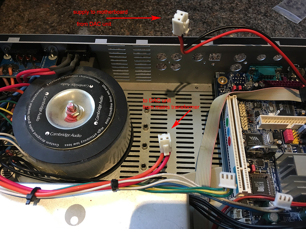
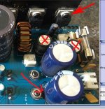
The first photo shows part of the 640H with the DAC unit removed. As can be seen there is a supply connection (pink and red cable) which connect to the DAC unit, and a connector (red and black) feeding the motherboard. As mentioned, for the good DAC unit the voltage measured to the motherboard is 12 volts and for the suspect unit 6 volts.
My suspicion is that the red and pink cables connecting into the DAC unit from the mains transformer both supply 6 volts. Just guessing that 6 volts is used for processing on the DAC unit and they combine to pass through 12 volts to the motherboard. This is just a theory and I may be talking nonsense, but it does explain why I only get 6 volts if somehow the combining parts are faulty.
The only piece of kit in proximity is the circular item with copper windings –again just wondered if this could have anything to do with combining the 2 voltages and if it could be faulty.
As I said just guessing and would love to hear any other explanations.
Many thanks
Alan C

 IMG_4007 by Alchad, on Flickr
 IMG_4005 by Alchad, on Flickr
I know my way around the inside of a computer, but am completely unfamiliar with anything using capacitors and resistors etc
By way of explanation before I get to my question, I have an old Cambridge Azur 640H music server - basically a mini PC with supposedly high end hifi bits inside. It stores music on a hard drive. I've had it for quite a few years and have undertaken various repairs/replacements and have grown quite attached to it, and very familiar with it's internals.
Anyway another one came up for sale on Ebay as "spares or repairs" and fancying a challenge I bought it. Swapping bits between the good unit and the Ebay one, I've narrowed the problem down to what I think is the DAC (?) unit which appears to transfer a 12 volt supply from the mains transformer to the motherboard. I can measure the voltage from the DAC unit to the motherboard and for the good unit it is 12 volts and for the Ebay one it is only 6 volts (this is with the DAC unit being fed from the same mains transformer) from the good unit.
I’ve tried to attach 2 photos which show the kit in question.
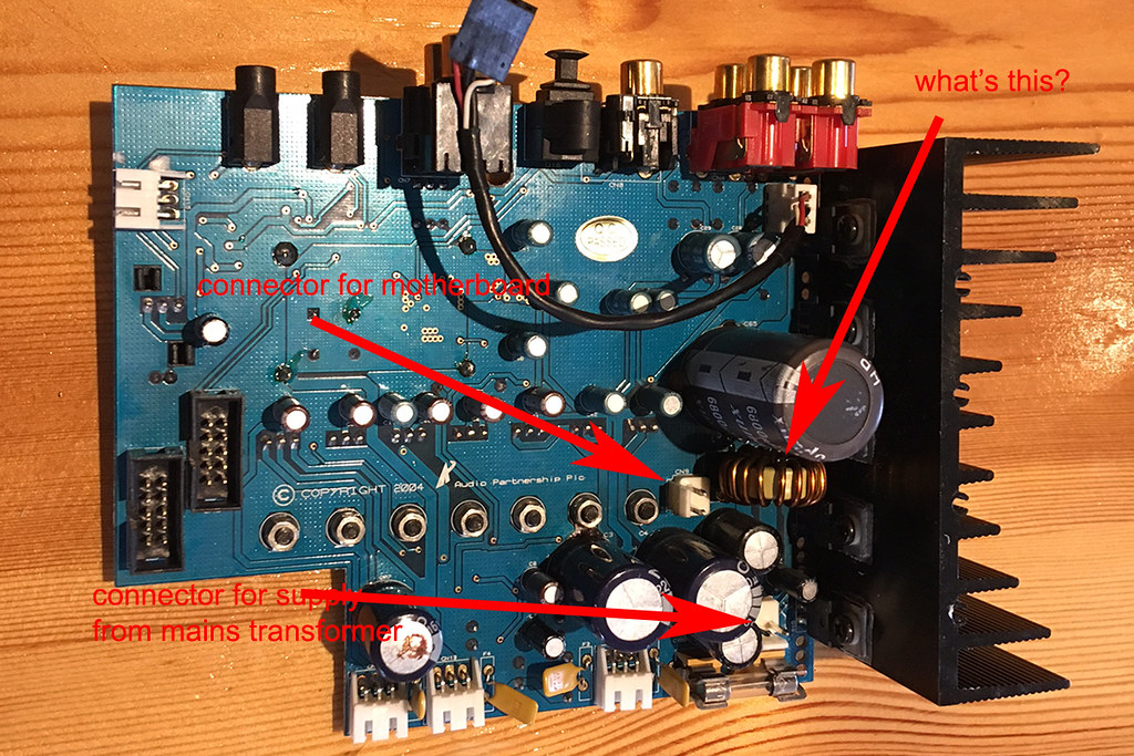
The first photo shows part of the 640H with the DAC unit removed. As can be seen there is a supply connection (pink and red cable) which connect to the DAC unit, and a connector (red and black) feeding the motherboard. As mentioned, for the good DAC unit the voltage measured to the motherboard is 12 volts and for the suspect unit 6 volts.
My suspicion is that the red and pink cables connecting into the DAC unit from the mains transformer both supply 6 volts. Just guessing that 6 volts is used for processing on the DAC unit and they combine to pass through 12 volts to the motherboard. This is just a theory and I may be talking nonsense, but it does explain why I only get 6 volts if somehow the combining parts are faulty.
The only piece of kit in proximity is the circular item with copper windings –again just wondered if this could have anything to do with combining the 2 voltages and if it could be faulty.
As I said just guessing and would love to hear any other explanations.
Many thanks
Alan C
IMG_4007 by Alchad, on Flickr
IMG_4005 by Alchad, on Flickr
You mean the Toroid Power Transformer."the circular item with copper windings"
maybe you mean an SMPS or some kind of regulator.the DAC unit from the mains transformer
PLEASE, stick to programming/software and avoid messing with plain *Electricity*, you can/will be hurt.
Sorry for the Politically Incorrect answer, it´s all about your safety.
Last edited:
You mean the Toroid Power Transformer.
Probably the cored inductor in the lower right part of the top picture.
Jan
You mean the Toroid Power Transformer.
maybe you mean an SMPS or some kind of regulator.
PLEASE, stick to programming/software and avoid messing with plain *Electricity*, you can/will be hurt.
Sorry for the Politically Incorrect answer, it´s all about your safety.
JM Fahey - thanks, not politically incorrect but slightly condescending. I am fully aware of the dangers of electricity and know where to tread and where not to. My question re the circular part with copper winding referred to the second photo and the question was repeated on the photo.
My main question remains why should I only be getting half the voltage, which I was hoping someone with your experience could help me with rather than offering safety fist advice.
Thread: Why only half voltage? Reply to Thread
I would see what you could turn up in the way of a revision history for this model -- or at least confirm that the serial #'s are some distance apart. The notion of exactly 6 volts appearing on a connector that, on another unit shows exactly 12 volts, sure hints 'Engineering Change Order' to me.
As to the other idea, the 'adding two 6V supplies' -- it would give the designer some bad headaches in regulation and stability. I've never seen it, at least in the commercial equipment on my bench.
Your 'what's this?' looks very much like the energy-storage inductor for a fairly high-current switching power supply (SMPS) -- probably several amps. If one board has it and the other doesn't, there's your E.C.O. Also, coils like that rarely fail; if it had, it would very likely show evidence of overheating.
Sounds like you're having fun and getting some brain exercise, though; apologies to JM.
--Rick
Thanks for the replies.
Just to update:-
Both DAC units appear to be absolutely identical.
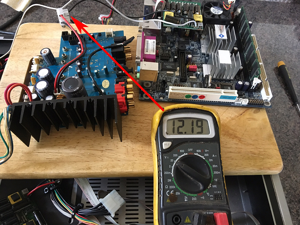
I did some more testing this morning - see photo - connecting each DAC in turn to the power supply and motherboard and measuring the voltage to the motherboard.
For the good unit the voltage was slightly in excess of 12 volts and I could get the motherboard to power up (CPU fan would spin). Also the CD drive would open/close.
For the faulty DAC the measured voltage varied from just under 12 volts to just over. However, the motherboard would not power up (CPU fan would give half a spin at most) and the CD drive would not operate.
One thing I hadn't mentioned before was that I was puzzled as to why I could not measure the input voltage to the DAC unit by applying the meter across the 2 pins on the underneath of the circuit board. It always read 0. Something made me try and measure it as an AC voltage and it turns out that the supply is about 19 volts AC !! I had just assumed it would come from the mains power transformer as a DC supply. So it appears that the DAC unit is converting from 19 volts AC to 12 volts DC.
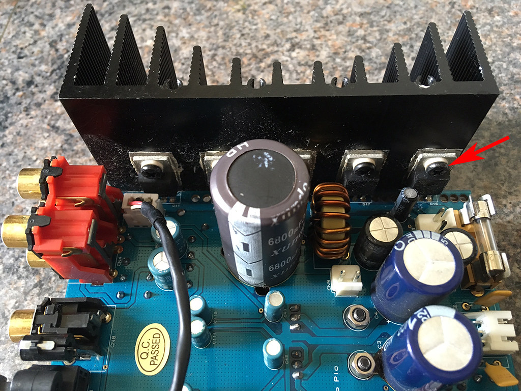
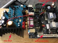
The second photo shows the rear part of the DAC unit where the power comes in from the transformer. The black finned item is a large heat sink, and attached to it are 5 electrical items (red arrow), each with 3 pins connecting to the circuit board. Googling the part number on the item they appear to be some form of voltage regulator. My best guess is that one or more of these has failed. It's about the best guess I can come up with and makes a bit of sense. One dark winter's day I might try replacing them !!
Any alternative theories, please advise.
Regards
Alan C

 IMG_4010 by Alchad, on Flickr
 IMG_4014 by Alchad, on Flickr
Just to update:-
Both DAC units appear to be absolutely identical.
I did some more testing this morning - see photo - connecting each DAC in turn to the power supply and motherboard and measuring the voltage to the motherboard.
For the good unit the voltage was slightly in excess of 12 volts and I could get the motherboard to power up (CPU fan would spin). Also the CD drive would open/close.
For the faulty DAC the measured voltage varied from just under 12 volts to just over. However, the motherboard would not power up (CPU fan would give half a spin at most) and the CD drive would not operate.
One thing I hadn't mentioned before was that I was puzzled as to why I could not measure the input voltage to the DAC unit by applying the meter across the 2 pins on the underneath of the circuit board. It always read 0. Something made me try and measure it as an AC voltage and it turns out that the supply is about 19 volts AC !! I had just assumed it would come from the mains power transformer as a DC supply. So it appears that the DAC unit is converting from 19 volts AC to 12 volts DC.
The second photo shows the rear part of the DAC unit where the power comes in from the transformer. The black finned item is a large heat sink, and attached to it are 5 electrical items (red arrow), each with 3 pins connecting to the circuit board. Googling the part number on the item they appear to be some form of voltage regulator. My best guess is that one or more of these has failed. It's about the best guess I can come up with and makes a bit of sense. One dark winter's day I might try replacing them !!
Any alternative theories, please advise.
Regards
Alan C
IMG_4010 by Alchad, on Flickr
IMG_4014 by Alchad, on Flickryou can attach clip on leads to two pins of each regulator and power on. that will let you monitor the voltage across those two pins.
Probing a live regulator can lead to accidental shorting and may damage anything.
You can work through all combinations of the three pins and then for all 5 regulators to see if any don't give expected readings.
Probing a live regulator can lead to accidental shorting and may damage anything.
You can work through all combinations of the three pins and then for all 5 regulators to see if any don't give expected readings.
Image 4005. Bottom left corner. Looks like the electrolytic is venting.
Could the drop of 6 volts be something putting excess load on the 12v rails ?
I agree caps could be a favourite failure item. Its very hard to tell in photos whether they have vented or not. The lower electrolytic looks a bit gungy... could be glue (normal) or it could have leaked.
The semiconductors... the three legged things on the heatsink... would be the least likely suspects at this stage.
Attachments
So suddenly the 6 volts is 12 volts againFor the good unit the voltage was slightly in excess of 12 volts and I could get the motherboard to power up (CPU fan would spin). Also the CD drive would open/close.
For the faulty DAC the measured voltage varied from just under 12 volts to just over. However, the motherboard would not power up (CPU fan would give half a spin at most) and the CD drive would not operate.

Mona
So suddenly the 6 volts is 12 volts again
Mona
Yes, it seems to vary every time I check it, since my post most times it's been about 12 but once or twice 6.
Someone suggested I try a 12volt car bulb on the supply from the DAC unit. The only bulb I had to hand was a tail/stop one (rated 4w one filament 21w the other). The 4w connection gave a reasonable if not brilliant light, the 21w connection was almost flashing on and off as though sufficient power wasnt getting through??
I've ordered some new capacitora and will have a go at replacing them and report back.
Regards
Alan C
Quote:
Originally Posted by Ketje View Post
So suddenly the 6 volts is 12 volts again
Mona
Weird.Yes, it seems to vary every time I check it, since my post most times it's been about 12 but once or twice 6.
Not sure whether you actually have different voltages at different times or there is some measurement problem.
Which might be anything , from poor test probe pressure to choosing the wrong "ground" point to refer measurement to .... to .....
Most probably the 12V supply can feed 4W, can not feed 21W , doubly so because a cold filament has very low resistance so far a fraction of a second it will pull way more than 21W and the supply self protects and auto turns off, then tries again.Someone suggested I try a 12volt car bulb on the supply from the DAC unit. The only bulb I had to hand was a tail/stop one (rated 4w one filament 21w the other). The 4w connection gave a reasonable if not brilliant light, the 21w connection was almost flashing on and off as though sufficient power wasnt getting through??
Not an indication that the supply is "bad" per se, it might just be doing its job.
A little Math tells us that a 21W bulb will pull close to 2 Amperes ... quite a bit more if cold ... yet most TO220 case regulators are rated 1 A .
What voltage do you get across the 4W bulb?
Any particular reason you suspect them?I've ordered some new capacitora and will have a go at replacing them and report back.
Same with:
Agree that you might have a bad regulator , specifically the 12V one.The black finned item is a large heat sink, and attached to it are 5 electrical items (red arrow), each with 3 pins connecting to the circuit board. Googling the part number on the item they appear to be some form of voltage regulator. My best guess is that one or more of these has failed. It's about the best guess I can come up with and makes a bit of sense. One dark winter's day I might try replacing them !!
But please don´t replace parts at random , simply because it often introduces new
problems, without solving the old ones.Agree with Andrew T´s ultra safe test procedure; a slipping tip, even worse two of them, handheld and real close may short and damage something else beyond (practical) repair.
That said, those are supposed voltage regulators which simplifies things a bit.
I suggest :
1) read all labels and write them over each one in the picture , so we know which is which.
2) something that simplifies this a little, is that all 3 leg regulators have only 3, specific legs (duh) so when measuring them we already expect what to find, it also makes it immediate what´s wrong.
The pins are
* Input (raw/unregulated) voltage.
* Output regulated voltage.
* Reference leg, which is often, but not always, ground.
So edit and repost that picture, also search each regulator datsheet and look at the pinout.
Here´s a few popular ones; see that they are all different so it´s important to identify which is which:
78xx
79xx

LM317
An externally hosted image should be here but it was not working when we last tested it.
so in a way this simplifies things a little: instead of dangerous pin to pin measuring, you *can* firmly attach black multimeter probe to ground and leave there, and with red probe measure voltage at each of the regulator legs.
Minor suggestion; legs are flat and hard, it´s easier to slip a meter tip; touching the solder pad instead is safer because solder is always softer, and meter tip "catches" a bit, it´s harder to slip.
In any case, be careful.
Last edited:
Many thanks for the comprehensive reply. Will try to answer your questions.
1) Why changing capacitors? My electrical knowledge is virtually zero, but reading around, they seem to get a bad press and listed as an item that often fails. I sort of figured that the big one which is physically very close to the input side off the DAC might be part of the voltage regulator side of the DAC so thougth changing wouldnt harm!
I have actually changed it this morning - no difference to the problem!!
2) 12 volt supply. Just to clarify something I may not have explained, or explained clearly. The 12 volt supply from the DAC unit feeds a small PSU which plugs into the motherboard. It's one of these
200 Watt DC-DC ATX
As you can see its rated up to 200w, so - and this remains my biggest puzzle -if I connect a 21w bulb across the 12volt supply to the PSU, surely it should just glow normally and not flash virtually on/off?
3) Re the 5 regulators, that was one of the other reasons I decided to change the capacitor so I could actually read the part numbers on all 5 of them. I will post the numbers later.
Once again thanks for the reply.
Alan C
OK, another update.
AS I mentioned in my first post this unit I'm playing with is one i bought "spares or repair" on EBay. I also have a good working unit which I've just removed the DAC board from and connected it up to the "spares/repair" unit psu and motherboard.
1) When connected up, I can get the motherboard CPU fan to spin by shorting out the switch pins on the motherboard, I cannot do this with the faulty DAC.
2) When I try the stop/tail bulb test to the power out of the good DAC unit, I get a strong solid light with no flashing which I do with the faulty unit.
Can't help but conclude something is serioulsy wrong with the voltage regulator side of the faulty DAC - could the flashing of the test bulb indicate it is trying to pass through AC voltage?
Re the 5 devices connected to the heat sink, 4 are coded
CQ 526 MBR 2045CTG
and the fifth
M50 PO3HDLG CQ550 (I think , very difficult to read).
I've googles but cannot find a pinout for the 2045CTG device, could anyone suggest how to test them?
Thanks again
Alan C
Last edited:
A lightbulb is a PTC resistor.Many thanks for the comprehensive reply. Will try to answer your questions.
1) Why changing capacitors? My electrical knowledge is virtually zero, but reading around, they seem to get a bad press and listed as an item that often fails. I sort of figured that the big one which is physically very close to the input side off the DAC might be part of the voltage regulator side of the DAC so thougth changing wouldnt harm!
I have actually changed it this morning - no difference to the problem!!
2) 12 volt supply. Just to clarify something I may not have explained, or explained clearly. The 12 volt supply from the DAC unit feeds a small PSU which plugs into the motherboard. It's one of these
200 Watt DC-DC ATX
As you can see its rated up to 200w, so - and this remains my biggest puzzle -if I connect a 21w bulb across the 12volt supply to the PSU, surely it should just glow normally and not flash virtually on/off?
3) Re the 5 regulators, that was one of the other reasons I decided to change the capacitor so I could actually read the part numbers on all 5 of them. I will post the numbers later.
Once again thanks for the reply.
Alan C
It starts off with a low resistance when cold and increases resistance as the temperature builds to the incandescent temp.
A 12V 21W bulb when fully powered will pass ~ 1.75A
That requires the hot resistance to be ~6.87ohms.
The cold resistance is likely to be around 7% to 10% of this, i.e. 0.7ohms to 0.5ohms.
That is an almighty load for a 200W ATX PSU, some of which goes to the lower voltage supplies.
The 12V supply might be protected to pass no more than 100W and maybe a lot less.
Last edited:
Thanks Andrew,
But regardless of the physics (?) it doesnt alter the basic fact that with the good DAC unit the motherboard fan spins as it should and also when the motherboard is replaced by a 21w bulb it lights up as it should. whereas with the faulty unit the fan doesnt spin and the bulb blinks on/off.
Just for clarity, below is a photo of the "test rig". Connecting the red and black wires powers the motherboard from the DAC unit for testing. If I remove the motherboard I just connect the bare red and black wires to the test bulb.
Regards
IMG_4025TEXT.jpg
Attachments
I've googles but cannot find a pinout for the 2045CTG device, could anyone suggest how to test them?
MBR2045CTG Datasheet(PDF) - ON Semiconductor
Also, (just to satisfy my curiosity), do you have a picture of the underside of the DAC board.
And if I may ask the experts bit of a novice question, why would the designers have a 12V dc supply comming from a19V ac line?
- Status
- This old topic is closed. If you want to reopen this topic, contact a moderator using the "Report Post" button.
- Home
- Amplifiers
- Power Supplies
- Why only half voltage?