Over the last few months I have been using and tweaking this for a 5v 1A shunt regulated supply for a Raspberry Pi based music server, http://http://www.analogmetric.com/goods.php?id=2211 and though I would share my findings with the forum members.
First of all I need to make clear that a lot of my findings have been based on simulated Spice CAD results (NI Multisim) and my test equipment is very basic, oscilloscope, frequency counter, dvm. Now this may ruffle a few feathers, but all measurements are comparative and the reason in sharing my findings is to offer them up to my peers for review and criticism even! Hopefully, someone with better equipment might try a few ideas and make some real world measurements? Glad to get that out of the way!
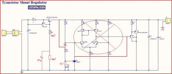
Now this kit gives excellent value for money and is of good quality, but it will not provided 1A @ 5v and it will only provide around 89dB of PSRR in its original form. However, a couple of simple mods will give the required current and significantly improve the PSRR. If you follow the link below it will give the schematic for reference.
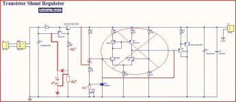
Mod 1 - to get 1A at 5v simply replace Q2 with a Darlington type, I used a TIP137, which is a pin for pin replacement for the MJ15031. The Darlington increases the vbe of Q2 to allow Q1 to turn on enough to enable the current source at this level. This mod also improves PSRR due probably to the higher hfe of the Darlington. R1 needs to be around 0.5Ohm to give 1A out.
Mod 2 - to improve PSRR even further, disconnect R4 (10k) from the junction of R3, D1 and Q3 and connect it directly to the +ve regulator output, i.e. collector of Q2. This is in line with the typical applications part of the TL431 datasheet. The pot will have to be adjusted to get the right Vout of 5v, but it is within its adjustment range. This mod increases PSRR to almost 140dB up to around 20KHz and from there it deteriorates back to around 88dB at 600KHz
There are further mods that can be carried out to improve PSRR even further over a wider bandwidth, but they require more "surgery". If this thread generates any interest then I will be happy to share those too.
I have used this modified regulator for a few months and can report that it has been rock solid and quiet and the sound quality improved with every mod that I tried.
Your feedback would be appreciated ladies and gents!
First of all I need to make clear that a lot of my findings have been based on simulated Spice CAD results (NI Multisim) and my test equipment is very basic, oscilloscope, frequency counter, dvm. Now this may ruffle a few feathers, but all measurements are comparative and the reason in sharing my findings is to offer them up to my peers for review and criticism even! Hopefully, someone with better equipment might try a few ideas and make some real world measurements? Glad to get that out of the way!
Now this kit gives excellent value for money and is of good quality, but it will not provided 1A @ 5v and it will only provide around 89dB of PSRR in its original form. However, a couple of simple mods will give the required current and significantly improve the PSRR. If you follow the link below it will give the schematic for reference.
Mod 1 - to get 1A at 5v simply replace Q2 with a Darlington type, I used a TIP137, which is a pin for pin replacement for the MJ15031. The Darlington increases the vbe of Q2 to allow Q1 to turn on enough to enable the current source at this level. This mod also improves PSRR due probably to the higher hfe of the Darlington. R1 needs to be around 0.5Ohm to give 1A out.
Mod 2 - to improve PSRR even further, disconnect R4 (10k) from the junction of R3, D1 and Q3 and connect it directly to the +ve regulator output, i.e. collector of Q2. This is in line with the typical applications part of the TL431 datasheet. The pot will have to be adjusted to get the right Vout of 5v, but it is within its adjustment range. This mod increases PSRR to almost 140dB up to around 20KHz and from there it deteriorates back to around 88dB at 600KHz
There are further mods that can be carried out to improve PSRR even further over a wider bandwidth, but they require more "surgery". If this thread generates any interest then I will be happy to share those too.
I have used this modified regulator for a few months and can report that it has been rock solid and quiet and the sound quality improved with every mod that I tried.
Your feedback would be appreciated ladies and gents!
Attachments
Nice work 🙂
What is the advantage of a shunt regulator in comparison to a LM1117 or similar?
Now that could be a loaded question! We all have our individual ideas and preferences, its a bit like driving a Ford or a BMW?
I first got into shunt regs in the 90s after reading Allen Wright's Tube Preamp Cookbook, a wonderful book and a well respected designer, now no longer with us.
The best analogy I can offer is that you can compare a series regulator to a class B (at best) amp and a shunt reg as a class A amp. The series reg works by switching on/off (very quickly) depending on load demand. The shunt device is fed by a constant current source and the shunt transistor varies according to load, but it is always on. Remove the load and all the set current is dissipated in the shunt device, short the output and all the current goes to the short, but it can be no more that what is set by the CCS, so in a way, it is inherently short circuit proof.
The other main advantage of the shunt reg is that it is bi-directional. In a series reg any transients generated on the load rails will bounce back against the series device output, causing it to switch off until the energy is dispersed somewhere. In a shunt reg, the transient is absorbed by the shunt device and error amp working in combination, thus leading to less unsettling of the load circuitry.
Now that has probably opened a can of worms!
You mentioned some good points in favor of shunt regulators!
Have you include output caps ESL/ESR in your simulation? This may be important for stability.
Cheers,
Udo
Have you include output caps ESL/ESR in your simulation? This may be important for stability.
Cheers,
Udo
I'm interested
Hi Druid,
I know little about SS but shunt regs, especially low voltage high current ones, are still generally thin on the ground so I would love to hear about your mods and your findings. Thank you, tim
Hi Druid,
I know little about SS but shunt regs, especially low voltage high current ones, are still generally thin on the ground so I would love to hear about your mods and your findings. Thank you, tim
No, diy=do it yourself ,why not let others do something too ? 😀Have you actually buld the regulator?
Mona
Sorry for the delay in replying, I have been away and only able to briefly view this post during that time. Many thanks for the contributions.
Udo, you brought up a good point about output capacitor ESL and ESR and the software does assume a perfect capacitor, so out of curiosity I put a 10mH inductor and 10R resistor in series with the output capacitor and all was well. There is a 100nF capacitor in parallel with the output cap, not 22uF as shown on the posted circuit diagram, so this will help reduce the ESR and ESL. As I have previously mentioned, I have been using this regulator for a while now and it is behaving perfectly. However, I am very grateful to you for bringing this up, because it caused me to investigate the regulator output more closely on simulation and whilst the basic mods cause no problems, the more modified version does show some very low level high frequency oscillation, which required a small fix. Bear with me and I will come back to this as I progress and learn how to post pictures of my simulation results on this thread.
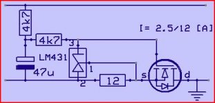
Mona, your idea of simplifying the design is a good one, it does actually give a PSRR of -112dB up to around 50KHz, deteriorating to -85dB at 600KHz, which is excellent performance. The error amplifier you have omitted basically gives the TL431 more gain, allowing greater PSRR. I have tried a few tweaks on this and it is possible to improve the PSRR to -130dB, so when I have learned the art of posting results, I will be happy to share those if you want?
Tim, low voltage shunt regulators are a challenge as they offer little voltage headroom for the error amp and other power transistors to operate. However, if they are configured to pull around 1A, which is the case here, they offer other advantages in allowing the introduction of choke regulation of relatively small values. Early in this thread I mentioned Allen Wright's influence on my thoughts some years ago an he was a big fan of choke regulation and so am I.
As I hinted above to Udo, the introduction of inductors can cause their own problems and so have to be treated with care and respect or they can actually make things worse!
Now to find out how to post pictures, many thanks.
Paul
Udo, you brought up a good point about output capacitor ESL and ESR and the software does assume a perfect capacitor, so out of curiosity I put a 10mH inductor and 10R resistor in series with the output capacitor and all was well. There is a 100nF capacitor in parallel with the output cap, not 22uF as shown on the posted circuit diagram, so this will help reduce the ESR and ESL. As I have previously mentioned, I have been using this regulator for a while now and it is behaving perfectly. However, I am very grateful to you for bringing this up, because it caused me to investigate the regulator output more closely on simulation and whilst the basic mods cause no problems, the more modified version does show some very low level high frequency oscillation, which required a small fix. Bear with me and I will come back to this as I progress and learn how to post pictures of my simulation results on this thread.
Mona, your idea of simplifying the design is a good one, it does actually give a PSRR of -112dB up to around 50KHz, deteriorating to -85dB at 600KHz, which is excellent performance. The error amplifier you have omitted basically gives the TL431 more gain, allowing greater PSRR. I have tried a few tweaks on this and it is possible to improve the PSRR to -130dB, so when I have learned the art of posting results, I will be happy to share those if you want?
Tim, low voltage shunt regulators are a challenge as they offer little voltage headroom for the error amp and other power transistors to operate. However, if they are configured to pull around 1A, which is the case here, they offer other advantages in allowing the introduction of choke regulation of relatively small values. Early in this thread I mentioned Allen Wright's influence on my thoughts some years ago an he was a big fan of choke regulation and so am I.
As I hinted above to Udo, the introduction of inductors can cause their own problems and so have to be treated with care and respect or they can actually make things worse!
Now to find out how to post pictures, many thanks.
Paul
The current source itself is the single largest contributor to psrr. Optimizing it should be the first thing on the agenda. Have a look at this thread. http://www.diyaudio.com/forums/solid-state/86626-searching-best-ccs.html
Also something to consider is what the output impedance vs. frequency looks like. It becomes a factor when thinking about use with audio circuits, not sure about pc power supply use though.
Also something to consider is what the output impedance vs. frequency looks like. It becomes a factor when thinking about use with audio circuits, not sure about pc power supply use though.
I couldn't agree more and many thanks for the link as I was unaware of the thread you highlighted.
What I found was that defining the best current source in isolation for a good shunt reg and vice versa is not the whole story as certain combinations seem to exhibit a sum greater than the parts. In other words the best current source configuration coupled with the best shunt regulator configuration may not be the best combination and I honestly don't know exactly why.
My best guess is that it comes down to some interaction between what is in essence a fixed current source feeding a controlled variable current source.
Although this thread is primarily aimed at using and modifying the Analog Metric SR50 Shunt Regulator, it has, as I hoped and expected, started to open further discussion on associated aspects of shunt regulator design, so if anyone has any further links to such threads please let me know. Otherwise I am happy to let it continue here, so please bring it on!
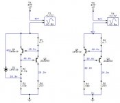
Hi Jerluwoo,The circuit on the left shows ~20dB improvement over the circuit on the right.
I get the same results on simulation too, around -30dB PSRR on right circuit and -50dB on left circuit.
I can see that the zener works, but dc conditions around the transistors remain the same and I honestly cannot see how it contributes to PSRR so could you enlighten me please?
Many thanks, Paul
The zener does the same thing as the chemical I proposed.That is keeping the power supply fluctuation away from the regulating part of the circuit around Q1.
You need extra current for the zener, that's not the case with a capacitor solution, witch I prefere (allows a greater resistor from ground )
Mona
You need extra current for the zener, that's not the case with a capacitor solution, witch I prefere (allows a greater resistor from ground )
Mona
When examining the circuit you have to also consider that there is also AC feedback along with the DC feedback. The zener does the same thing as a capacitor would by bootstrapping the collector of the sense transistor and increasing it's gain along with increasing feedback. Using a zener lets this effect work all the way down to DC without causing a delayed start up like a large capacitor would, which may cause issues in some circuits. Zeners only need 1-2 mA for optimal operation, the beta and current output of the pass transistor plus the current where the sense transistor is at optimum in its HFE curves will dictate how high a resistance can be used to feed from ground.
Hi Druidaudio
I also bought the SR50 kit, but in my case to power a preamp with around 18 - 25v.
I've only just finished building mine, and haven't yet tested it, so I'd very much appreciate if you could give me an idea how much volts you'd reckon on loosing across the unit to get it working efficiently (so I can work out what voltage transformer I'd need for it?).
Hi,
Sorry, just picked this up, so apologies for not responding sooner.
You need to drop at least 5v across the current source, more if you can, but that depends on what the total current draw of the circuit, including the shunt reg, will be.
In the output voltage range you require, it would seem you will need around 22v secondaries.
Hope this helps?
Paul
Over the last few months I have been using and tweaking this for a 5v 1A shunt regulated supply for a Raspberry Pi based music server, http://http://www.analogmetric.com/goods.php?id=2211 and though I would share my findings with the forum members.
First of all I need to make clear that a lot of my findings have been based on simulated Spice CAD results (NI Multisim) and my test equipment is very basic, oscilloscope, frequency counter, dvm. Now this may ruffle a few feathers, but all measurements are comparative and the reason in sharing my findings is to offer them up to my peers for review and criticism even! Hopefully, someone with better equipment might try a few ideas and make some real world measurements? Glad to get that out of the way!
Now this kit gives excellent value for money and is of good quality, but it will not provided 1A @ 5v and it will only provide around 89dB of PSRR in its original form. However, a couple of simple mods will give the required current and significantly improve the PSRR. If you follow the link below it will give the schematic for reference.
Mod 1 - to get 1A at 5v simply replace Q2 with a Darlington type, I used a TIP137, which is a pin for pin replacement for the MJ15031. The Darlington increases the vbe of Q2 to allow Q1 to turn on enough to enable the current source at this level. This mod also improves PSRR due probably to the higher hfe of the Darlington. R1 needs to be around 0.5Ohm to give 1A out.
Mod 2 - to improve PSRR even further, disconnect R4 (10k) from the junction of R3, D1 and Q3 and connect it directly to the +ve regulator output, i.e. collector of Q2. This is in line with the typical applications part of the TL431 datasheet. The pot will have to be adjusted to get the right Vout of 5v, but it is within its adjustment range. This mod increases PSRR to almost 140dB up to around 20KHz and from there it deteriorates back to around 88dB at 600KHz
There are further mods that can be carried out to improve PSRR even further over a wider bandwidth, but they require more "surgery". If this thread generates any interest then I will be happy to share those too.
I have used this modified regulator for a few months and can report that it has been rock solid and quiet and the sound quality improved with every mod that I tried.
Your feedback would be appreciated ladies and gents!
Thank for your mod. Nice work!
- Home
- Amplifiers
- Power Supplies
- Use and mods to Analog Metric SR50 Shunt Regulator