can I use a simple NTC Thermistor for the transformer? can you recommend me which one to go with ? or any complex circuitry is needed for
3.3kva Toroidal / R-core trafo with 1,00,000uf per rail capacitance or it can even go for 2,00,000uf per rail capacitance.
Please recommend me some reliable way to handle inrush currents. Im using relays but apart from that there should be a inrush current limiting to be taken care. please suggest me that using a NTC Thermistor is ok? If so what is the best way to do it? where to place that ?
100mF or 1F?
Why you need so high capacitance?
You will need around 30-50 seconds to charge safety this capacitance.
The diodes peak current will be huge, 10's of KA and the conduction time will be maybe under micro-seconds generating a lot of noise in a very large spectrum.
This high capacitance will generate only problems solving almost nothing.
For a delayed start-up for transformer you need only to search the forum or the internet.
The in rush current on a trafo that side will likely pop your mains side domestic fuses. IF you have included any. And that's without the capacitance factored in.
Perhaps a large "puck" thyristor bridge, firing angle ramped over a period of time, to the capacitors? Monitoring current as feedback for the angle ramp rate?
Or try and find a 3.3kva variac.
Or series of contactors switched in sequence, switching current limiting resistors.
Perhaps a large "puck" thyristor bridge, firing angle ramped over a period of time, to the capacitors? Monitoring current as feedback for the angle ramp rate?
Or try and find a 3.3kva variac.
Or series of contactors switched in sequence, switching current limiting resistors.
Last edited:
rhythmsandy, what is the max continuous power to be drawn from the power supply, as that will be part of the assessment to determine an NTC.
You will also need to indicate the DC voltage of the supply, as that will be a major part of the assessment of the rise time of the DC voltage.
Also what is your mains AC voltage, as that will determine the primary side current levels needed.
Without basic information like that I'm surprised anyone could give a useful response.
And then there are the application questions as to what are you using the supply for.
NTC = not such a good idea.
I use a series resistor shunted by a big relay. You can manually control the relay with a two position switch or use a timing circuit. I've done both.
If you use the former, be sure to use LARGE wattage power resistors, since you could, might just forget to flip the switch. It's been done.
The 10 ohm value is about right - you can test and figure it out empirically.
I used ~500,000ufd total at about 60vdc in my Symphony No.1 Amplifier.
_-_-

Well yeah, but I think a cap multiplier that will supply the current I needed would be about the same size as the amplifier's output stage, and need the same heatsinking, and might not deliver quite the same as the cap bank. Then too there is the issue of IF it will sound as good or the same.
Quite frankly, given the lack of larger "computer grade" caps in this century, a cap multiplier starts to look very good... of course there are other wild and wooly capacitors in massive multiples one can consider I guess.
Quite frankly, given the lack of larger "computer grade" caps in this century, a cap multiplier starts to look very good... of course there are other wild and wooly capacitors in massive multiples one can consider I guess.
Perhaps all good points. But the OP's issue is the inrush current, which for a CM is frankly significantly lower than for a standard capacitor bank.Well yeah, but I think a cap multiplier that will supply the current I needed would be about the same size as the amplifier's output stage, and need the same heatsinking, and might not deliver quite the same as the cap bank. Then too there is the issue of IF it will sound as good or the same.
Quite frankly, given the lack of larger "computer grade" caps in this century, a cap multiplier starts to look very good... of course there are other wild and wooly capacitors in massive multiples one can consider I guess.
+1
That would be my preferred option.
I'm planning on using 68000uF to 0.1F in a chipamp PSU with a 300-500va trafo, so smaller scale.
There was a thread that discussed the psu capacitance for a chipamp and IIRC it's conclusion was that, you don't gain anything if you use more than 2200uF.
Gajanan Phadte
NTC = not such a good idea.
i agree, perhaps a 100ohm 100 watt resistor like Dales...
that is how i will do it....
For safety reasons, seriously high power PSUs should only be built by people who really know what they are doing. The necessary safety features add significantly to the cost and complexity of the PSU, so others will be tempted to omit them or not even realise that they are necessary.
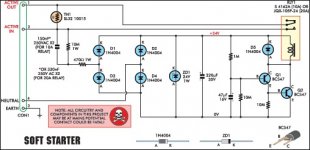
I always run the relay off a secondary small and dedicated supply. But the schematic put up by andrewlebon is pretty much the standard way to do the timed cap method. I have also used a 555 timer chip.
As far as the Dale resistors, the type in the aluminum case, I do NOT like them, as they tend to explode out the ends when they are pushed near or above their rated power. I prefer the cylindrical ceramic type, they can handle quite a bit over their rating for rather long periods, even to the point of starting to glow red.
SMPS? How do you get the residual HF artifacts down low enough? Most SMPS do not like to look into a big capacitive filter. Not sure that it is cost effective to use a big choke either... Thus far the noise and other EMI seem to be problematic?
- Status
- Not open for further replies.
- Home
- Amplifiers
- Power Supplies
- inrush current limiters for 3.3kva and 1,000,000uf per rail capacitors?