I would like some advice on winding a switching transformer, the transformer I would like to make is from this schematic for this car smps.
The schematic calls for a transformer with 4 turns a centre tap and another 4 turns for the primary. and around 9 turns a centre tap and another 9 turns for the secondary.
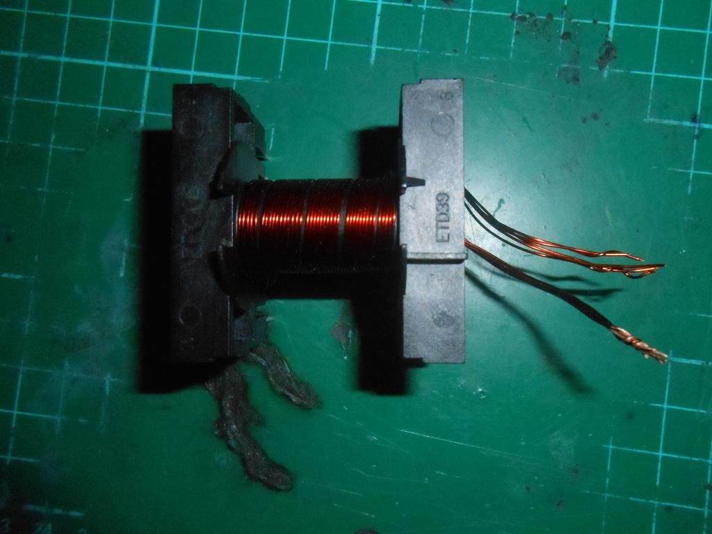
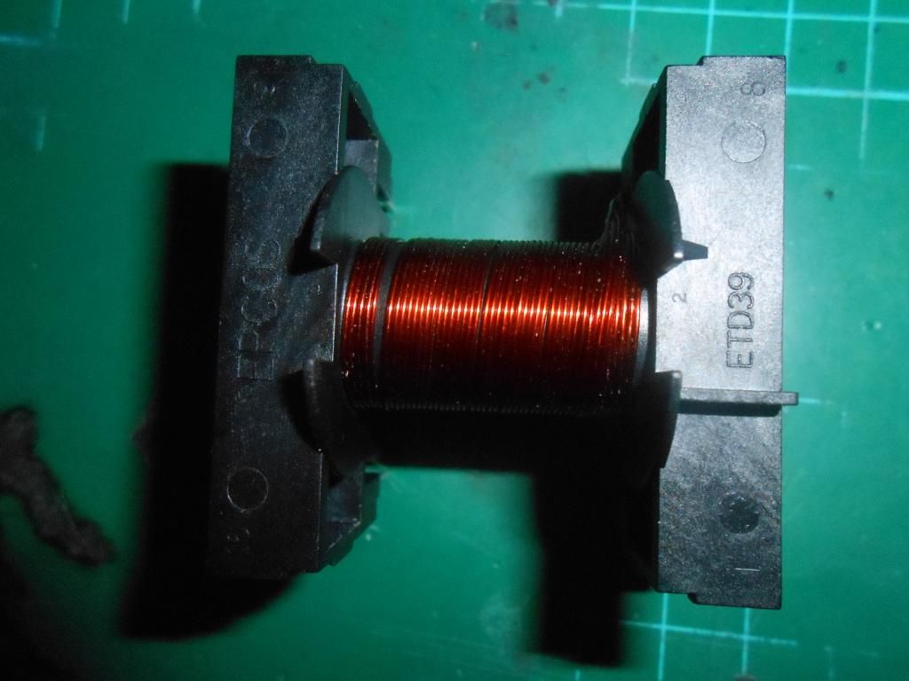
I'm using an epcos ETD39 core as they look easier to wind and mount on an pcb. I'm using 5 strands of 0.45 mm insulated copper wire for the primary.
This image show the winding of the first part of the primary. I've started to wind the primary clockwise for no reason.
I plan to wind the second part of the primary inbetween the first one.
Is the the correct way to do it?
Another question do half turns count as windings? As you have to make a "half turn" to get outside of the bobbin.
If not theres only essentially 3 full turns per primary on this transformer.
My thought is that the 2 half turns, one at the start and the other at the end would count as a fourth full turn.
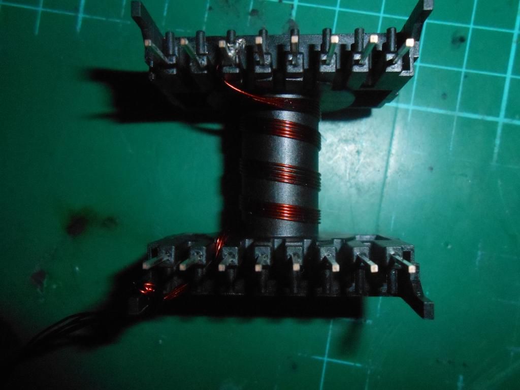
Another view from the top of the transformer makes it seem it has 4 full turns.
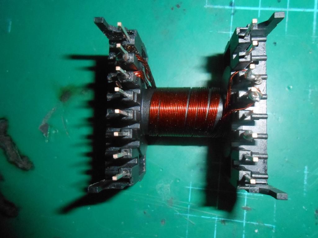
This image shows the second part of the primary wound between the first part in the same direction.
There are no overlaps of the copper wire and the winding are as tight as I could get them.
There is still some empty space on the transformer, I don't think this is probably good.
I've tried to keep the windings as neat and as uniformed as possible with no overlaps as before.
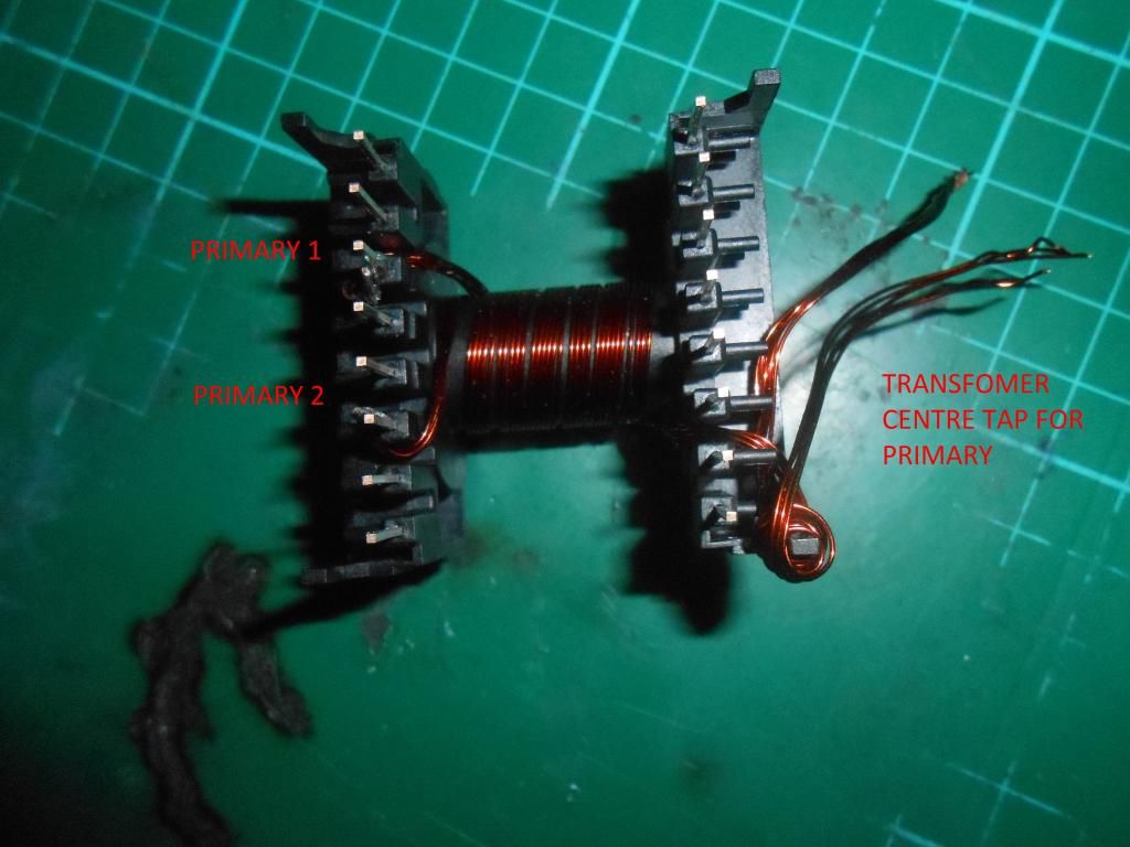
With this last picture I've added some captions.
Any advice would be much welcomed. I've seen plenty of information about switching transformers but no real practical building/winding of the transformer core itself.
Thank you.
The schematic calls for a transformer with 4 turns a centre tap and another 4 turns for the primary. and around 9 turns a centre tap and another 9 turns for the secondary.
I'm using an epcos ETD39 core as they look easier to wind and mount on an pcb. I'm using 5 strands of 0.45 mm insulated copper wire for the primary.
This image show the winding of the first part of the primary. I've started to wind the primary clockwise for no reason.
I plan to wind the second part of the primary inbetween the first one.
Is the the correct way to do it?
Another question do half turns count as windings? As you have to make a "half turn" to get outside of the bobbin.
If not theres only essentially 3 full turns per primary on this transformer.
My thought is that the 2 half turns, one at the start and the other at the end would count as a fourth full turn.
Another view from the top of the transformer makes it seem it has 4 full turns.
This image shows the second part of the primary wound between the first part in the same direction.
There are no overlaps of the copper wire and the winding are as tight as I could get them.
There is still some empty space on the transformer, I don't think this is probably good.
I've tried to keep the windings as neat and as uniformed as possible with no overlaps as before.
With this last picture I've added some captions.
Any advice would be much welcomed. I've seen plenty of information about switching transformers but no real practical building/winding of the transformer core itself.
Thank you.
Your windings look plenty neat. I didn't do any counting of turns but surely you can. It is possible to make half turns through any shell core but you have to pass through one of the outer legs to do it. Certainly balance in a push pull is far more critical than even primary inductance or ratio. So long as the legs of each winding and tap leads pass outer legs the same number of times you have fundamentally balanced windings. Winding uniformity and lead dress does affect coupling and leakage but you're doing a good enough job so far. It's obviously not an off-line transformer but I'd still recommend a good turn or two of mylar between pri/sec. A little space doesn't hurt. With a little care you can use it for end margin to keep the whole winding under tape. Proper construction actually.
The first pic shows a winding that starts and finishes on the same side of the core, so no half turns there.
The first pic shows a winding that starts and finishes on the same side of the core, so no half turns there.
Last edited:
Thank you for your reply. It's good to know i'm heading down the right direction. I'm not sure what you mean by " passing through the outer legs" to make half turns. You say that balance is make important than the turns ratio or primary inductance .
What would happen if the transformer was unbalanced? My guess is you get excessive heating of the mosfets/ transformer windings as one is working harder than the other.
I was going to use standard black electrical tape to cover the primary winding, But I don't think people here would forgive me😀
Should the secondary winding be wound in the opposite direction from the primary winding to minimise inter-winding coupling? This holds true for an toroidal core.
There are two windows of the core that hold windings, formed by a center pole and two legs. Passing through only one of them makes a half turn. With only 4 turns primary, a half turn difference on one side of the center tap would send the core into saturation immediately at much less than 12v b+. So long as you don't do that and have no shorts, your transformer is likely to work fine. It looks like the bobbin could hold more wire, but if it doesn't heat up too much, it's good. Even masking tape is more fun to wind over than vinyl. With a good tape layer it wont make much difference which way you wind the secondary on this transformer.
I'm wondering why your transformer has so few turns on it? Like you, I'm concerned that you're using only a small part of the winding area. These two observations are ringing alarm bells in my mind that something's astray.
Care to share your calculations for the primary inductance? If you're using the core ungapped, perhaps this is why you've got so few turns - normally transformers like this are used gapped.
Care to share your calculations for the primary inductance? If you're using the core ungapped, perhaps this is why you've got so few turns - normally transformers like this are used gapped.
Well, taking a closer look at the last image, it looks like you're about to drive the transformer push push, which will be a bigger problem than anything we discussed so far. Unfortunately, if you start both halves of the primary in the same direction, a "crossover" connection is required from one start to one finish for the center so you end up forcing flux in the core in opposing directions by the two sets of grounded source power switches. Or, you can have your neater termination at the center by winding one half primary in the opposite direction. You'll have to take care of that one way or the other or it will be disappointing.
Other than that, 4 turns on a 1/2" core is not "scary". Depends on frequency and actual B+. If the core starts getting hot at idle you have the choice of adding turns or turning up the frequency. Ungapped cores are common enough, including solid toroids. The wire is too light for 380 watts but it really depends on how hard you actually intend to load the supply.
Other than that, 4 turns on a 1/2" core is not "scary". Depends on frequency and actual B+. If the core starts getting hot at idle you have the choice of adding turns or turning up the frequency. Ungapped cores are common enough, including solid toroids. The wire is too light for 380 watts but it really depends on how hard you actually intend to load the supply.
An ungapped toroid used as a trafo? Never seen that - do you have an example? Metal powder toroidal cores don't count as they have what's known as 'distributed gaps' 😛
Ferrite almost exclusively. It's kind of important to make sure your per-leg duty cycle doesn't vary much cycle by cycle, turns are the same, resistances are the same, switches are the same. If you do all that, it stays balanced and works pretty well. Soft start keeps it from crashing before it gets off the ground. I know it looks insane to anyone used to staring at circuits that go to 30Hz with DC bias and hundreds of drive volts. DC to DC converters used in autosound power amp supplies are heavily dominated by ungapped toroid cores.
Last edited:
I can only imagine they might get low enough inductance for a trafo if using NiZn ferrite materials, however they're not too common and tend to be more expensive than MnZn.
I'll just do a little math here for the OP - my Ferroxcube data for ETD39 core shows an ungapped AL around 3000. So with 4 turns this gives a primary inductance of 48uH. With no airgap though this'll saturate the core way too quickly for a decent power output.
I'll just do a little math here for the OP - my Ferroxcube data for ETD39 core shows an ungapped AL around 3000. So with 4 turns this gives a primary inductance of 48uH. With no airgap though this'll saturate the core way too quickly for a decent power output.
MnZn almost exclusively. 3C8 n stuff. In these designs the current keeps going through the windings in nearly exact opposite every 5uS or so. No saturation.
Last edited:
I'm wondering why your transformer has so few turns on it? Like you, I'm concerned that you're using only a small part of the winding area. These two observations are ringing alarm bells in my mind that something's astray.
Care to share your calculations for the primary inductance? If you're using the core ungapped, perhaps this is why you've got so few turns - normally transformers like this are used gapped.
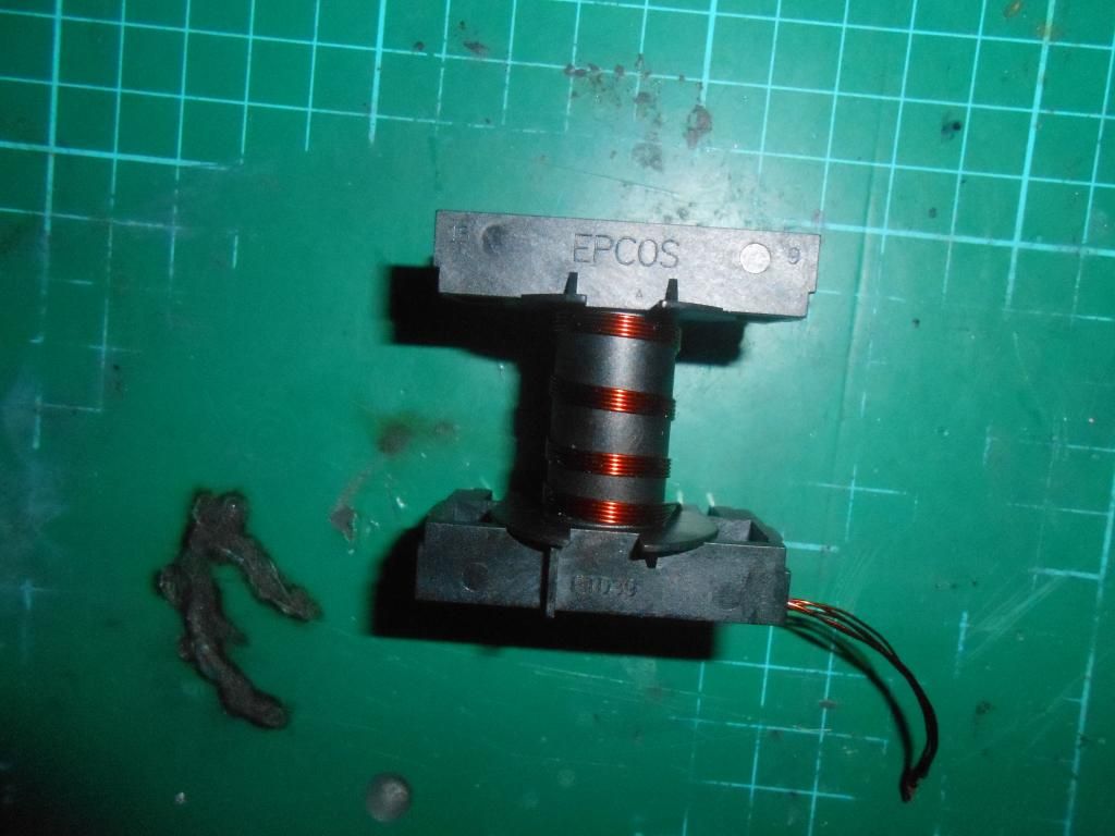
I've adding another second turn on both primary winding's to help fill up the core more.
As for the calculations I don't have any. I've been following along with this guide.
Switchmode Power Supply For Car Audio
My biggest concern with using the ETD39 core is that the calculations may be different then the toroid core the guide used.
I will have to put off winding the secondary as i don't have any suitable tape to insulate the primary winding, not even any masking type.
Here's what the transformer looks like now.
That'll run. Just make sure to connect one pri winding start to the other pri winding finish for the center tap. The ESP instructions to wind both primaries in the same direction only works if you *continue* the second winding from where the first one left off, which effectively turns the current around in both directions from the resulting free ends.
The basic circuit is the usual poop, with no inductor between the output rectifiers and filter capacitors. This means that the output caps will peak detect and the PWM control will not have much effect to control output voltage unless dialed to a tiny sliver. Typical LCD crap design that has been floating around for years on end.
That'll run. Just make sure to connect one pri winding start to the other pri winding finish for the center tap. The ESP instructions to wind both primaries in the same direction only works if you *continue* the second winding from where the first one left off, which effectively turns the current around in both directions from the resulting free ends.
Sorry both primary winding DO run in the same direction "clockwise" are you saying this is correct? As for the center tape I was going to connect all the winding's to one pin for the center tap, but thought it would be best to combine two legs due to the current requirements.
On your transformer as you have wound it, you must connect one start to the other finish to make a center tap.
The basic circuit is the usual poop, with no inductor between the output rectifiers and filter capacitors. This means that the output caps will peak detect and the PWM control will not have much effect to control output voltage unless dialed to a tiny sliver. Typical LCD crap design that has been floating around for years on end.
They work even better open loop with a linear post-regulator. 😉
The basic circuit is the usual poop, with no inductor between the output rectifiers and filter capacitors. This means that the output caps will peak detect and the PWM control will not have much effect to control output voltage unless dialed to a tiny sliver. Typical LCD crap design that has been floating around for years on end.
It does actual mention about adding output inductors in the guide to improve
regulation. as for the design its simple but if it works then great!! Just want to see if i can get it working. sure there no feedback loop what a proper SMPS
has, but its not something I would use all the time either.
On your transformer as you have wound it, you must connect one start to the other finish to make a center tap.
Yes I understand that bit thank you😀
My biggest concern with using the ETD39 core is that the calculations may be different then the toroid core the guide used.
Normally ESP is pretty comprehensive, but here I'm not so sure - he seems to imply that the ETD trafo he suggests and any toroid you happen to find of the right size will behave identically in his circuit. 😱
A metal powder toroid will have a much lower AL value (typically in the low 100s of nH) whereas your ETD is around 3000. So I'm rather at a loss here to understand why the primary inductance isn't important.
I'll bow out and watch how this develops from the sidelines I think 🙂 I do agree totally with your concerns.
<edit> Ah I see - he never did actually wind his own ETD trafo, he got that picture from a commercial unit. This could explain a lot.....😛
Last edited:
Normally ESP is pretty comprehensive, but here I'm not so sure - he seems to imply that the ETD trafo he suggests and any toroid you happen to find of the right size will behave identically in his circuit. 😱
A metal powder toroid will have a much lower AL value (typically in the low 100s of nH) whereas your ETD is around 3000. So I'm rather at a loss here to understand why the primary inductance isn't important.
I'll bow out and watch how this develops from the sidelines I think 🙂 I do agree totally with your concerns.
I guess I can always try an toroid core if this one does not work correctly😀 I guess its all practice winding transformers. Do you have cores that you can recommend? I will probably have to buy it off ebay.
- Status
- Not open for further replies.
- Home
- Amplifiers
- Power Supplies
- Help With Winding a Switching Transfomer