Hello again, I was wondering if anyone has ever made a quiet tube rectified power supply for a Tube preamp?
I'm looking to provide 300 VDC, at 50 milliamps. I already have an Edcor Transformer, 5AR4, 22uf 500 volt, and then Hammond 10H 100m choke, that I will feed several PI filters to bring the rippled and voltage down.
However, whenever "I" build a supply like this, I still have a decent amount of noise present. This could be ME< or it could be the supply- I don't know.
But I'm thinking that regulating that 300 VDC is the way to go, perhaps with a chip?
That's what I'm looking to you folks for advice for.
Any ideas welcomed")
Aric
I'm looking to provide 300 VDC, at 50 milliamps. I already have an Edcor Transformer, 5AR4, 22uf 500 volt, and then Hammond 10H 100m choke, that I will feed several PI filters to bring the rippled and voltage down.
However, whenever "I" build a supply like this, I still have a decent amount of noise present. This could be ME< or it could be the supply- I don't know.
But I'm thinking that regulating that 300 VDC is the way to go, perhaps with a chip?
That's what I'm looking to you folks for advice for.
Any ideas welcomed
Aric
22µF looks a bit flimsy for the task of smoothing 50mA, but anyway, it doesn't make much difference: even if you increased it to 100µF, it would only bring a ~12dB improvement, which is sizeable but not enough to gain complete quietness.22uf 500 volt, and then Hammond 10H 100m choke, that I will feed several PI filters to bring the rippled and voltage down.
This means that DF96's explanation is probably right: there must be something wrong in your wiring. Probably the ground, but there may be other possibilities too.
If you post your exact circuit, it can be simulated to evaluate how much ripple you'll really incur (with a perfect wiring).
You could use something like this.
MOSFET Regulator
But You would have to change the mpas92,42 to mpsa94,44 and the feedback resistor R9 to about 68K.
MOSFET Regulator
But You would have to change the mpas92,42 to mpsa94,44 and the feedback resistor R9 to about 68K.
Check out the 'Maida regulator'. It's a LM317 regulator used in a configuration to allow for high voltages. Good performance, low parts count and a proven design. I've build several with great results. My current preamp (2x 12ax7) uses one at 325V. I don't have the exact numbers at hand, but the ripple is in the few milivolt range. Morgan Jones (I own the 3rd edition) has a great section on the design, but lot's can be found here on the forum and elsewhere online.
My advice diy Salas Simplistic HV version 2: http://www.diyaudio.com/forums/power-supplies/134801-simplistic-mosfet-hv-shunt-regs.html
Schematic Image
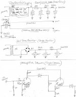
Thanks for the replies and sorry for the delay. I'm going to try the PSU in a seperate chassis, with an umbilical cable to the preamp, with conductors of 14/4.
The plan is to send 12 VDC down two wires of the cable, and the 300 volts down the other two.
The preamp has 4 separate channels, 2 are 12ax7 phono stage left and right, and the other 2 are 12ax7 line level preamp channels.
This is a continuation of a project I was building a few weeks back which I decided to scrap.
I am laying out this one from scratch, and really want to get the noise floor down as much as possible.
Please ignore the SS rectifier supply in the drawing I will not be using that, but rather will be using the Tube Rectified version above it.
The second picture is an RIAA stage for the phono that I am implementing into the desgin.
Attachments
I would use the choke with SS as well as the tube rectifier . That would let you increase the cap value without increasing the peak load on the transformer average would be about he same.Thanks for the replies and sorry for the delay. I'm going to try the PSU in a seperate chassis, with an umbilical cable to the preamp, with conductors of 14/4.
The plan is to send 12 VDC down two wires of the cable, and the 300 volts down the other two.
The preamp has 4 separate channels, 2 are 12ax7 phono stage left and right, and the other 2 are 12ax7 line level preamp channels.
This is a continuation of a project I was building a few weeks back which I decided to scrap.
I am laying out this one from scratch, and really want to get the noise floor down as much as possible.
Please ignore the SS rectifier supply in the drawing I will not be using that, but rather will be using the Tube Rectified version above it.
The second picture is an RIAA stage for the phono that I am implementing into the desgin.
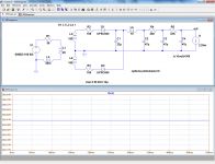
With such a filter, the noise will be vanishingly small: it is below the default resolution of LTspice.I am laying out this one from scratch, and really want to get the noise floor down as much as possible.
Since the p-p ripple on C3 is ~215µV and the final RC brings an additional 60dB, the result should be 215nV. Unlikely to cause problems. If you still get hum, that simply means there is something wrong in the wiring.
Note that the supply will be capable of providing only 2.3mA for a 300V output.
From a purely academic perspective, the circuit is improvable: if you make R4 and R5 approximately equal (15K + 18K for example), you will gain a few tens of dB quietness, should that matter...
Attachments
Elvee, thank you.
The transformers HV secondary is rated at 570 C.T. 220 ma. Is the circuit itself, or the limit of the 100ma choke what's going to keep me from having more than net 2.3 ma?
I plan on providing 300 volt for a total of (4) 12ax7 tubes.
Is there anything I can do to improve upon this power supply circuit without getting overly complex?
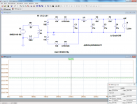
Mainly the final 33K resistor.Elvee, thank you.
The transformers HV secondary is rated at 570 C.T. 220 ma. Is the circuit itself, or the limit of the 100ma choke what's going to keep me from having more than net 2.3 ma?
You can reduce it to taste, but of course this will affect the ripple level, as will the output current.
Since you have quite a margin, this shouldn't be a problem
Apart from tweaking the resistor's values to get the best result for a given current, no.Is there anything I can do to improve upon this power supply circuit without getting overly complex?
You could always increase the size of the filter caps, or add another RC, but this looks unnecessary.
You may need to be careful with subsonic problems, as your PSU has quite a high subsonic output impedance due to the 33k resistor. In general, it is not a good idea to make a PSU for a much higher voltage then drop the surplus across a big resistor.
Your circuit diagram did not make clear the grounding arrangements, which will be the decider on hum (given so many smoothing sections).
Your circuit diagram did not make clear the grounding arrangements, which will be the decider on hum (given so many smoothing sections).
DF, I will change those two resistors to 15k and 18 k respectively however I guess the grounding layout is what I'm mainly here to ask about today since the regulation, etc. isn't the actual issue causing hum.
My plan was to have the CT, and smoothing caps star grounded with a bridge between them and the external power supply chassis, then run that star ground down a length of 14 gauge wire to the preamp chassis ground.
The ground in that box is simple a piece of 10 gauge romex ground wire, that is isolated from the chassis of the preamp box, then bridged to the chassis with a 15 ohm, .1uf cap in parallel with each other.
So my "thought" was to connect all cathode grounds, volume control grounds, and signal grounds to the 10 gauge wire in the preamp, then have them ground to the 14 gauge wire in the umbilical cable that runs back to the power supply.
Thoughts?
If you are not going to be pulling much current, and the 12ax7 does not, what you could do is to use the LR8 regulator along with a pass transistor. You can easily make it adjustable. I forget where the write up is about using this regulator, but it's either here or at diyaudioprojects. I have used them for tube phono/preamp circuits and they work very well.
Here is a site with a schematic for you:
LR8N3 Voltage Regulator
You will notice that the circuit looks very much like using a pass transistor with any other 3 terminal regulator. Not overly complex, you can build it on a small perf board, and it works.
I used a horizontal output transistor in my supplies simply because I had them available and they would take the voltage that I needed. Just make sure that you heat sink the transistor that you use. I used a to92 socket for the LR8 (it is a to92 part) so if I fried the LR8 I could just yank it out and drop another one in. That makes prototyping very easy if you make a mistake.
Hope this helps.
A 12AX7 triode typically uses a mA or two. Four 12AX7 might use 10-20mA? Why use a 220mA transformer for 20mA?
Never use star grounding in a PSU. It almost guarantees hum. Use a bus. Transformer CT at one end - the noisy end. Capacitor negatives along the bus, in order. The quiet end of the PSU ground bus then connects to the signal ground, and so becomes the negative supply.
Never use star grounding in a PSU. It almost guarantees hum. Use a bus. Transformer CT at one end - the noisy end. Capacitor negatives along the bus, in order. The quiet end of the PSU ground bus then connects to the signal ground, and so becomes the negative supply.
So if there was a ground bus in front of me (indicated by a ----- line), would it look like this?
Power supply C.T.----1st cap gnd-----2nd cap gnd-----30th cap gnd--------------------------------------------------------------------------------------------------------------------------------1st cathod gnd-----2nd cathode gnd-----volume control gnd-----signal ground?
Power supply C.T.----1st cap gnd-----2nd cap gnd-----30th cap gnd--------------------------------------------------------------------------------------------------------------------------------1st cathod gnd-----2nd cathode gnd-----volume control gnd-----signal ground?
- Status
- This old topic is closed. If you want to reopen this topic, contact a moderator using the "Report Post" button.
- Home
- Amplifiers
- Power Supplies
- Power Supply for Tube Preamp