Thank you so much for your help!
And thanks for suggestions, the value 80 but I had found among the specifications of pre-amp, but I will use the values that you suggested to me. I hope to find resistance here it's all closed (food and pharmacies aside)
Third-week living closed at home almost all the time, here in Italy.
Stay at home stay safe enjoy lots of music.
Francesco.
CLC is better but be aware of a choke's possible hum field if in proximity with signal gain stages. 450uF is heavy and can promote charge up spike. Are you familiar with PSUD?
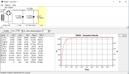
PSUD 2.10 released
You can predict a smooth configuration with that one. By adding some extra R. Even small capacitors can be enough (and faster) for small load current (CCS mA) resulting to small ripple pk-pk if with CLC. Shoot for a smooth ramp up and no more than 1V pk-pk ripple I would say.
PSUD 2.10 released
You can predict a smooth configuration with that one. By adding some extra R. Even small capacitors can be enough (and faster) for small load current (CCS mA) resulting to small ripple pk-pk if with CLC. Shoot for a smooth ramp up and no more than 1V pk-pk ripple I would say.
Hi Salas
finally, I have recuperated the resistance to do the tests.
At the moment I have the following problems my transformer has a 200 0 200 output and once CRC they become 260v so it is not good for the shunt?
Is it normal that with 200AC after the bridge (4x MUR 860G) plus filter capacitors and resistors I have 260DC?
I would have expected 280V full bridge rectified from a 200VAC secondary. This shunt can work steadily even with only 10V in-out difference, so if the transformer is low or the R in the CRC too high, you could go for 250V reg output. If the R in the CRC can not help enough by choosing a lower value one.
Hi Salas,
I’m using the output for B+ can you help me to understand where what it’s wrong ?
Thanks
Francesco
I’m using the output for B+ can you help me to understand where what it’s wrong ?
Thanks
Francesco
An externally hosted image should be here but it was not working when we last tested it.
The board in the link is Tube-I-zator V2.0, I don't have a ratification board. You can suggest a good resistance value, in my parts bins, have two capacitors 100uf 450v one 330uf 400v one 220uf 450v a few resistances of different values and the diodes Mur860 and 1n4007 and four bridges GBPC2504, GBPC2506, GBPC2508, DB3501.
")
The transformer's loss spec is just assumed. Its not your transformer at your average mains level. So the resistor is ballpark value.
Adjust it smaller by paralleling another one if the output voltage falls short in reality. I set CCS load at 40mA for some leeway though.
Adjust it smaller by paralleling another one if the output voltage falls short in reality. I set CCS load at 40mA for some leeway though.
- Home
- Amplifiers
- Power Supplies
- Simplistic MosFET HV Shunt Regs