Thanks sergiu2009, looking good, the picture of ur amp are a bit small, hard to see. i read the patent fast, damn its always so hard to follow ") haha. but it comes down to slits and cuts to reduce mass, as you already metnioned early. i will giive it a try in a few hours. i wont be ussing the method of supending the membrame i like the elastic aprouch better more room of correction
haha. but it comes down to slits and cuts to reduce mass, as you already metnioned early. i will giive it a try in a few hours. i wont be ussing the method of supending the membrame i like the elastic aprouch better more room of correction
haha. but it comes down to slits and cuts to reduce mass, as you already metnioned early. i will giive it a try in a few hours. i wont be ussing the method of supending the membrame i like the elastic aprouch better more room of correctionOh, sory for that, the upload site did that. The bellow picture are good.
upsyde
radiator with the stack effect
http://s7.postimg.org/naskp0e47/IMG_3179.jpg?noCache=1433088454
radiator insyde
the metal case from insyde
a syde of the radiator
upsyde
An externally hosted image should be here but it was not working when we last tested it.
radiator with the stack effect
http://s7.postimg.org/naskp0e47/IMG_3179.jpg?noCache=1433088454
radiator insyde
An externally hosted image should be here but it was not working when we last tested it.
the metal case from insyde
An externally hosted image should be here but it was not working when we last tested it.
a syde of the radiator
An externally hosted image should be here but it was not working when we last tested it.
oh i always use the attachments. and us half the resulotion my iphone takes (its an old 3gs)
well i tested with the mid portion removed in the coil. lost 3 grams, and only a minor diference in the 2 to 6 Khz range.
then i made some slots outside the coil around the coil. again some diference in the same range.
after that i tried slits where the bending starts for the cylinder. lost a decent amount of material but results in measurement is nothing, slightly drop in output even. so the place where the cylinders meet is a no go to do anythign with. it has to be in the coil area.
should not be hard to think of something to get rid of most the material that connects the two cylinders and the coil. maybe lose th inner part of the coil , and (or most of it like they do with the holes in the patent) then perforate the **** out of the the rest then glue the paper cylinder to the ends of this structure. its funny since the rest of the weight in the cylinders or how hard they are to move around does not influencey the high frequencys at all. if i put tension on the strings. (so it moves in and out with some more effort when you push) it does not at all effect the frequency response.
well i tested with the mid portion removed in the coil. lost 3 grams, and only a minor diference in the 2 to 6 Khz range.
then i made some slots outside the coil around the coil. again some diference in the same range.
after that i tried slits where the bending starts for the cylinder. lost a decent amount of material but results in measurement is nothing, slightly drop in output even. so the place where the cylinders meet is a no go to do anythign with. it has to be in the coil area.
should not be hard to think of something to get rid of most the material that connects the two cylinders and the coil. maybe lose th inner part of the coil , and (or most of it like they do with the holes in the patent) then perforate the **** out of the the rest
then glue the paper cylinder to the ends of this structure. its funny since the rest of the weight in the cylinders or how hard they are to move around does not influencey the high frequencys at all. if i put tension on the strings. (so it moves in and out with some more effort when you push) it does not at all effect the frequency response.
Last edited:
oh i always use the attachments. and us half the resulotion my iphone takes (its an old 3gs)
well i tested with the mid portion removed in the coil. lost 3 grams, and only a minor diference in the 2 to 6 Khz range.
then i made some slots outside the coil around the coil. again some diference in the same range.
after that i tried slits where the bending starts for the cylinder. lost a decent amount of material but results in measurement is nothing, slightly drop in output even. so the place where the cylinders meet is a no go to do anythign with. it has to be in the coil area.
should not be hard to think of something to get rid of most the material that connects the two cylinders and the coil. maybe lose th inner part of the coil , and (or most of it like they do with the holes in the patent) then perforate the **** out of the the rest
Hello my friend,
Believe it or not the the bigger you go with the cylinders, ex Janus 50, 70 the more you accentuate the high frecvency response and flatten the rest.. A bigger influence factor is the contact between the coil and the membranes. The more weight you add to the cylinders you lose efficency.
To lose more of your impedance peaks, you have to make an overhung coil structure.. If it is underhung, and the magnetic gap isnt large enought and the mebranes arent stiff enought to keep the coil in the gap, the coil goes out of the gap, gets hot and the impedance goes higher at that time...
The solution is a clever overhung design with a bigger gauge or continue in undergung design by using a smaller diameter wire and tighten the elastics that centeres the coil in the gap so that the coil remains in the gap all the time.
Look at the elastics from the two pictures bellow:
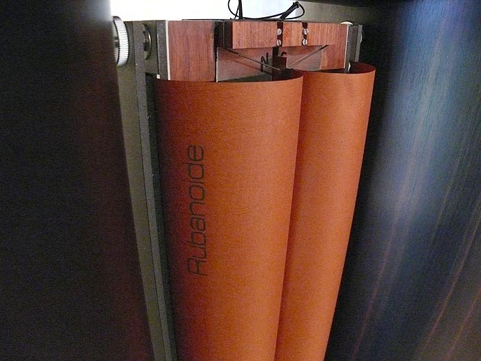
This elastic smart "trick" will keep the coil centered in the gap, linearise the impedance, and get rid of some nasty resonances. The elastic is tighten in two points on the chasis here and one point on the cylinders...
And now look at the picture bellow :

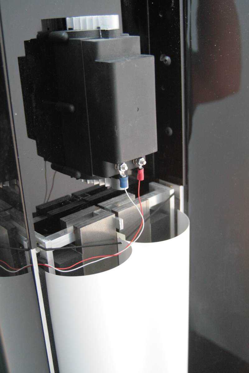
As you can see the elastic is tighten in one point not in two points (like in the two pictures above) on the chasis and lets the coil move freely in the gap.. If in this third pic the magnets arent strong enought or if it isnt overhung design it will have impedance peaks just like you have.
Please keep this in mind.
Cheers
Sergiu
WrineX
How about a Silhouette-type cutter to cut aluminum traces for your coil? I know you've seen the discussions of that approach in other threads. Seems like it could be useful for your project.
Few
its to thick
i might get my printer today or tomorow, so i can do a test to see if it prints on alumnium foil laminated on a sort of carier, maybe even right on the menbrame itself.- sergiu2009, those peaks have nothing to do with the elastic config, really i tested it myself. and i got a underhung coil an i already use the elastic style like picture 3 atm and used also the config like pic 1 abd 2, actually like fig 2 and 3 but i forgot to make a place on the top and botom plates to space the the 2 elastics forward and sideway from the middle. to center both the depth of the coil and the sideways play.
well i got measurements with and without the foam pad on the edges of the cylinders wich drops distortion around 155hz, it adds weight as well but i dont see a loss in output to be honest.
if i can make coils easy and leight i can more easy try differend kind of weight and materials.
Could it some how be that the force of the magnet gap is just not big enough? for the fast movement required for the last 5khz.
i could ofcourse try to go from 5 mm gap to 3.5 or 4 would increase considerable the power. when i got flat coils its also more easy to get it in a smaller gap.
its to thick
- sergiu2009, those peaks have nothing to do with the elastic config, really i tested it myself. and i got a underhung coil an i already use the elastic style like picture 3 atm and used also the config like pic 1 abd 2, actually like fig 2 and 3 but i forgot to make a place on the top and botom plates to space the the 2 elastics forward and sideway from the middle. to center both the depth of the coil and the sideways play.
Interesting. The elastic should influence these impedances and frecvency "bumps"... Strange thing.. Thank you for your imput. I really apreciate it.
well i got measurements with and without the foam pad on the edges of the cylinders wich drops distortion around 155hz, it adds weight as well but i dont see a loss in output to be honest.
In your case, with smaller magnets, you should have had a loss in dB. Strange thing.
You where right, this speaker really is strange.
if i can make coils easy and leight i can more easy try differend kind of weight and materials.
If you can make flatter coil you can do that. Or use smaller gauge on the wire. From my experience with rewinding of burned woofer coils i can tell for shure that if you use 0.18 mm gauge wire you have a maximum 50w sinus speaker, and 0.22mm is for 100w sinus.
Could it some how be that the force of the magnet gap is just not big enough? for the fast movement required for the last 5khz.
i could ofcourse try to go from 5 mm gap to 3.5 or 4 would increase considerable the power. when i got flat coils its also more easy to get it in a smaller gap.
You can be shure of that. Your magnets are not strong enought to keep the coil ferm in an 5mm gap. Use thinner iron plates, and lower you gap.
Then please tell us about your findings because it will be a big change..
Cheers
Sergiu
Hello WrineX, congratulation to you : I follow you like a fan.
Regards the impedance, you might try a copper tape over the iron into the gap in front the coil. The high conductivity of the copper should reduce the inductance of the coil. This is a common trick used with standard speaker too.
Regards the impedance, you might try a copper tape over the iron into the gap in front the coil. The high conductivity of the copper should reduce the inductance of the coil. This is a common trick used with standard speaker too.
Sorry, can you clarify what it is that is too thick? The Al foil? I was imagining using foil that is thin enough to be cut, and then using multiple layers of traces (insulated from each other) if you need to build up more conductor length. Maybe there's a reason that's impractical--I haven't sat down to sketch out what would be involved. That said, it seems like you could use heavy aluminum tape intended for sealing heating ducts as the foil. It's heavier than kitchen foil but probably not too thick to cut. Kapton tape could serve as the substrate and insulator. Just a thought...
Do you use 10mm steel bars?
If you use 8mm the field gets stronger.
Be aware of flux in iron .Keep it below 1,8T. for standard steel.
Bernt
yeah i use 10 mm, my thoughts about that was that the coil would be longer in the gap. at higher volume and lower frequency's. but you might be right i maybe just go back to 8. to increase the field.
Hello WrineX, congratulation to you : I follow you like a fan.
Regards the impedance, you might try a copper tape over the iron into the gap in front the coil. The high conductivity of the copper should reduce the inductance of the coil. This is a common trick used with standard speaker too.
thats nice to hear, not posting for nothing then
about the copper, do i just tape it on the metal that face the coil ? and what could be the results>? Sorry, can you clarify what it is that is too thick? The Al foil? I was imagining using foil that is thin enough to be cut, and then using multiple layers of traces (insulated from each other) if you need to build up more conductor length. Maybe there's a reason that's impractical--I haven't sat down to sketch out what would be involved. That said, it seems like you could use heavy aluminum tape intended for sealing heating ducts as the foil. It's heavier than kitchen foil but probably not too thick to cut. Kapton tape could serve as the substrate and insulator. Just a thought...
Aah now i get it. i tried this with aluminium foil tape (40 micron)and used tape as barrier, i never posted it since the result was the same and i could not get the resistance high enough.
I did receive my solid ink printer yesterday, after some cleaning, it prints
thats a good thing. now i wait on my copper laminate foil. or i might just try one on aluminium just for fun only got 10 micron alu kitchen foil laying around. and the Foil from Bernt ! wich are both to thin for this purpose and dont want to spoil the nice foil from Bernt so i might need to laminate some thicker kitchen foil to mylar to test if this whole contraption works for me
Last edited:
Well made a quick laminate of 10 micron alu kitchen foil, spray glue and some sort of giftwrap foil but not the crackling one. a thicker foil that does not make any sound on its own. excact thickness i dont know , could measure it but thats not the point. btw to get a prety nice laminate heat one of the 2 components(the foil or the carrier, foil in this case) and spray the glue on the warm/hot part, you get a super nice even coat.
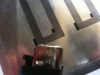
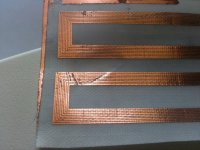
made a lamination cut a piece out and stick it on a a4 paper to go into the printer. and there is a print as seen in the picture, they are pretty thin lines
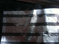
well now the problem , i used caustic soda to etch since i know it eats aluminium, but somehow my mask is letting lose! onooooo, maybe i am etching to fast? or should i just get normal good Ferric Chloride. i did clean the foil with a rubbing sponge and then some alcohol. but literally all the maskr just floats in the solution within 3 minutes. damned!
made a lamination cut a piece out and stick it on a a4 paper to go into the printer. and there is a print as seen in the picture, they are pretty thin lines
well now the problem
, i used caustic soda to etch since i know it eats aluminium, but somehow my mask is letting lose! onooooo, maybe i am etching to fast? or should i just get normal good Ferric Chloride. i did clean the foil with a rubbing sponge and then some alcohol. but literally all the maskr just floats in the solution within 3 minutes. damned!Attachments
Last edited:
weird , i also dropped a laminate in there wich i had made previously paper on alu, just to see how flat it would be. here it does stay on , even more funny is because it was on peper the paper gets soaked, after a while the alumninium and the solid ink just sperate from the paper , you then end up with a coil without backing just aluminium and the solid ink i dont see any use for that yet. but i tell me i made some dumb mistake with my laminate why everything came of in an instant.
just aluminium and the solid ink i dont see any use for that yet. but i tell me i made some dumb mistake with my laminate why everything came of in an instant.WEll tried different things, i cant get the ink to adhire to AL, or etching screws everything up ,i dont know, i even used the foil from bernt, also failure. i even went to the shop for some hydrochloric acid. wich resulted in the same story.
I had this problem before, even with etch resist(wich has its purpose to not come off) , the stuff is used in art world.
Everytime i use aluminium the resist comes of, tried, paint ,toner,solid ink, etch resist, tape, al just comes off..
So next thing was to see if its only on ALU or also on copper clad ?
I had only 0.5 mm pcb around, way to thick for my printer. so i leveled 0.35 of with my cnc... dirty job wont recommend to do it again, this dust is a killer.
Ofcourse i just made the thing to short, for a complete coil, but it will be usefull to know if i bought the damn printer for nothing.
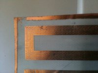
So i stuck it to a paper and hit PRINT. to bad i had the paper set on transperency, this results in thickker lines then usually and with this small ofset of the lines it can smear a bit. so the result is far from awesome. BUT the resist does not come off. stays where it should be ! and looking promising for the sheets i bought. the laminates i bought dont have glass fibre like this pcb, you can see that the 2 layers of fibre make a mesh and you can also see that this affects the etching, the lines looke a bit wobly. i noticed this after i printed it, so some of the ink gets deeper in the material then other parts hence the size increases. and thats why it look so ragged. i scratched the lower coil few times when the ink was applied to see if i could remove it, as you can see.... yes you can.
But still look at the clearance, almost there! this is with 0.3mm spacing and its even les because i had it set on transperency.. im a happy camper again after this aluminium nightmare.
now just wait for the mail man, to see if it works on a good copper laminate
I had this problem before, even with etch resist(wich has its purpose to not come off) , the stuff is used in art world.
Everytime i use aluminium the resist comes of, tried, paint ,toner,solid ink, etch resist, tape, al just comes off..
So next thing was to see if its only on ALU or also on copper clad ?
I had only 0.5 mm pcb around, way to thick for my printer. so i leveled 0.35 of with my cnc... dirty job wont recommend to do it again, this dust is a killer.
Ofcourse i just made the thing to short, for a complete coil, but it will be usefull to know if i bought the damn printer for nothing.
So i stuck it to a paper and hit PRINT. to bad i had the paper set on transperency, this results in thickker lines then usually and with this small ofset of the lines it can smear a bit. so the result is far from awesome. BUT the resist does not come off. stays where it should be ! and looking promising for the sheets i bought. the laminates i bought dont have glass fibre like this pcb, you can see that the 2 layers of fibre make a mesh and you can also see that this affects the etching, the lines looke a bit wobly. i noticed this after i printed it, so some of the ink gets deeper in the material then other parts hence the size increases. and thats why it look so ragged. i scratched the lower coil few times when the ink was applied to see if i could remove it, as you can see.... yes you can.
But still look at the clearance, almost there! this is with 0.3mm spacing and its even les because i had it set on transperency.. im a happy camper again after this aluminium nightmare.
now just wait for the mail man, to see if it works on a good copper laminate
Attachments
Last edited:
Sorry, can you clarify what it is that is too thick? The Al foil? I was imagining using foil that is thin enough to be cut, and then using multiple layers of traces (insulated from each other) if you need to build up more conductor length. Maybe there's a reason that's impractical--I haven't sat down to sketch out what would be involved. That said, it seems like you could use heavy aluminum tape intended for sealing heating ducts as the foil. It's heavier than kitchen foil but probably not too thick to cut. Kapton tape could serve as the substrate and insulator. Just a thought...
the minimum width is to wide i should have said
when you use a siloutte, stacking them is an option but then you add allot of extra weight on it as well, only with the tape. on the other hand you will have much bigger power handling then the laminate coil solution about the copper, do i just tape it on the metal that face the coil ? and what could be the results>?
yes stick the copper over all the metal part facing the coil,both sides (yuo can also try to close the tape as a loop but I not sure if this make any diifference).
What happens...the phisic tell us if you put a non ferromagnetic conductor close the coil, the pruduced eddy currents make (almost) null the magnetic field produced by the coil itself. This mean that the coil has no inductance and, this mean the impedece is lower at high frequancy and finally means you improve the high frequency response of your loudspeaker.
There is enother big advantage you can have adding some pieces of copper: thi improve the linearity....but this is another story
verry cool, i knew normal drivers have it somtimes, but did not it was that simple
i got some copper foil wich i could try tomorow., does it has to be thick ? or does it not really mater?. alumnium could work as well if i understand correct. is there a reason why copper is prefered?i could make a measurement of the impedance and see what happens
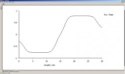
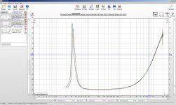
Here is a measurement without and with copper tape on the inside of the gap, i did not connect both sides to eachother, might be doing that in a final version with a bit more solid tape or foil. this stuf is only 40 micron or something.
pink is with no tape
green is with. most weird is overal the resisance is higer and where it peaks its a bit lower. be it only 0.6 ohm or something
is this the result i should expect? the copper layer consist of 8 pieces of thin copper tape side by side, i can imagine it works better with like 0.1 mm copper out of one piece, making a loop?
Attachments
Last edited:
- Home
- Loudspeakers
- Planars & Exotics
- A DIY Ribbon Speaker of a different Kind