@bolserst
I like the article on the neodymium magnets.
But most of us have no control over what happens to the magnets that we buy.
Even on my end of the food chain which is as close as it is possible to get. I depend on the referral of people I know well to send me to quality magnet producers.
Most of the magnets I use are zinc electroplated. And there is a conflict between plating thickness and motor strength. The greater the distance from the magnet to the steel in the motor the greater the loss in potential motor strength. The best coating is epoxy. The worst coating for magnetic motor strength is of course epoxy.
Hello Folks,
Again thank you for the wealth of information you all have been sharing!
Would something like 1 yard - 200/80T Yellow x 50" Width Silk Screen Printing Mesh Fabric New | eBay be a better alternative to speaker grill cloth? Assuming that it was going to be tightly stretched across?
Thanks,
jsa_ind
Again thank you for the wealth of information you all have been sharing!
Would something like 1 yard - 200/80T Yellow x 50" Width Silk Screen Printing Mesh Fabric New | eBay be a better alternative to speaker grill cloth? Assuming that it was going to be tightly stretched across?
Thanks,
jsa_ind
Hi,
I also have a question as to the strength of magnets to be used. As you have seen the present magnets are all corroded and need to be replaced. I am unable to determine the strength of the magnet. Can someone please advise if I could just take a N55 magnet strip that has the same dimensions as the present lot and replace them? Or has the magnetic strength be exactly equal to the original magnets?
Thanks,
jsa_ind
Hi,
I also have a question as to the strength of magnets to be used. As you have seen the present magnets are all corroded and need to be replaced. I am unable to determine the strength of the magnet. Can someone please advise if I could just take a N55 magnet strip that has the same dimensions as the present lot and replace them? Or has the magnetic strength be exactly equal to the original magnets?
Thanks,
jsa_ind
N55 is not needed. Most of the work done in rare earth magnets is to allow the magnet itself to work at higher temperatures. In the case of voice coil type linear motors ( normal woofers) you have an enormously inefficient motor type that produces a great deal of heat. Most loudspeakers are in the order of 2% efficient in converting electricity in to force. Heat quickly becomes a problem when you have for all intense purposes an electric stove element being used to help move around a cone. Magnets are very close in the motor and tend to really warm up in high power applications.
A planar has some good things going for it in home application. Lots of open area. Relatively low lower input for the frequency range of interest.
So below I posted two types of neodymium magnet material. They are pretty wide apart in the numbering scheme.


Look in the line Maximum Energy Product.
There is a fair difference in the numbers presented.
The curves are for demagnetization. The temperature where the magnet begins to loose it's strength.
N42 is pretty good for a planar that is not trying to be used in Pro-sound. Openly I don not know what was use din the Monsoon design. But I'm giving you a middle of the road suggestion. If you go to strong on the magnet you end up with an over damped motor. So you end up trading efficiency for loss in low frequency output. Remember loudspeakers like to have your cake and eat it to!
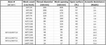
Nice findWould something like 1 yard - 200/80T Yellow x 50" Width Silk Screen Printing Mesh Fabric New | eBay be a better alternative to speaker grill cloth? Assuming that it was going to be tightly stretched across?

A seller of silk screen mesh that actually gives thread diameter and pore sizes. 🙂
I took the seller’s table and added a column showing the estimated acoustic resistance in Rayle.
The 80T fabric you linked to has Ra not that much higher than tightly stretched grill cloth. I would suggest using the 100T or 120T fabric instead.
1 yard - 300mesh/120T Yellow x 50" Width Silk Screen Printing Mesh Fabric New | eBay
Attachments
Thank you so very much Bolsert! You have been such a great help!! I will purchase the 300 mesh/120T fabric as advised!
Bolsert, Lowmass & Mark I had a few more questions, could you please assist?
Is there any advantage of stretching & gluing the 300 mesh/120T fabric in the front of the speaker as well?
Apart from a notch filter are there any other mechanical means of reducing/eliminating cavity resonance? Stuffing the "inbetween's" with fiberglass/angel hair wouldn't be a solution I guess with the damping material moving with the diaphragm.
Is it safe to assume that cavity resonances would translate into increase of impedance on the graph after the fundamental resonance frequency of the driver? Or can cavity resonances also crop up before the resonance frequency of the planar driver.
How does one differentiate between the resonance frequency & cavity resonances in a planar driver?
Thanks
Bolsert, Lowmass & Mark I had a few more questions, could you please assist?
Is there any advantage of stretching & gluing the 300 mesh/120T fabric in the front of the speaker as well?
Apart from a notch filter are there any other mechanical means of reducing/eliminating cavity resonance? Stuffing the "inbetween's" with fiberglass/angel hair wouldn't be a solution I guess with the damping material moving with the diaphragm.
Is it safe to assume that cavity resonances would translate into increase of impedance on the graph after the fundamental resonance frequency of the driver? Or can cavity resonances also crop up before the resonance frequency of the planar driver.
How does one differentiate between the resonance frequency & cavity resonances in a planar driver?
Thanks
what i noticed is they are usually above 10Khz range depending on thickness of magnets. mesh wont help you there 🙁
Bolsert, Lowmass & Mark I had a few more questions, could you please assist?
Is there any advantage of stretching & gluing the 300 mesh/120T fabric in the front of the speaker as well?
Apart from a notch filter are there any other mechanical means of reducing/eliminating cavity resonance? Stuffing the "inbetween's" with fiberglass/angel hair wouldn't be a solution I guess with the damping material moving with the diaphragm.
Is it safe to assume that cavity resonances would translate into increase of impedance on the graph after the fundamental resonance frequency of the driver? Or can cavity resonances also crop up before the resonance frequency of the planar driver.
How does one differentiate between the resonance frequency & cavity resonances in a planar driver?
Thanks
If I were in your shoes. Mount your newly re-magneted driver and listen to what you have. If you have the ability measure what you have. Measuring is as simple as an IM-6 mic from Parts Express and the Audio Tool app by Julian Bunn.
Then assess what you have. If you want to play with damping you have a few choices. You can go with the learn as you go method. Might be a good one for you. Taking a baseline measurement is a good idea because we have a crazy ability to believe that every change we make is better. Many times it is not really better, just different.
You will have little ability to effect cavity resonances and they will be quite high up in the response to begin with. There will be cancellation effects across the planar ahead of any cavity effects. Your mounting baffle will have greater effects than many other things and treating the baffle itself with an absorber should produce some interesting and potentially useful effects.
It would make the front and rear response identical as possible, if this is a design goal. But then again, when using mesh, you will only see a small < 1dB difference in the mid and treble range if you only used the mesh on the back. The main thing is to make sure you have damped the diaphragm resonance enough so it isn’t limiting your output capability at and below the crossover. Basically, measure the near-field response before and after applying mesh to the rear frame as mwmkravchenko recommended. If you need more damping, add some mesh to the front frame as well.Is there any advantage of stretching & gluing the 300 mesh/120T fabric in the front of the speaker as well?
For dipole use, there is no acoustic way I am aware of to damp the cavity resonance without ruining the rest of the response...you have to handle it electrically. In monopole use, it can be done, but you have to play with the damping and back chamber size/shape a good deal to get what you want.Apart from a notch filter are there any other mechanical means of reducing/eliminating cavity resonance? Stuffing the "inbetween's" with fiberglass/angel hair wouldn't be a solution I guess with the damping material moving with the diaphragm.
An alternative is to ditch the front plate and magnets like Magneplanar.
You avoid the cavity resonance on the front side but will lose sensitivity and some linearity.
Some measurement of a BG Neo8 with front plate removed here: diy-ribbon-dipole-tweeter-Post#185
If interested, I posted a simple lumped model for determining cavity resonance.
diy-ribbon-dipole-tweeter-Post#196
Comparison of theory vs measured on the BG Neo8 cavity resonance.
diy-ribbon-dipole-tweeter-Post#202
The diaphragm resonance frequency is determined by diaphragm tension and mass of airload(which is proportional to square root of the area of the diaphragm). It will tend to be in the 50hz - 500Hz range. As mentioned previously in Post#21, since the diaphragm resonance is at frequencies where wavelength is larger than the size of the diaphragm(ka<1), adding mesh will help damp it.Is it safe to assume that cavity resonances would translate into increase of impedance on the graph after the fundamental resonance frequency of the driver? Or can cavity resonances also crop up before the resonance frequency of the planar driver. How does one differentiate between the resonance frequency & cavity resonances in a planar driver?
The cavity resonance is mainly determined by the diaphragm mass and the compliance of the air layer between the diaphragm and the magnets and frame. See Post#185 linked to above for more details. Due to the lightness of the diaphragm and the thinness of the air layer, the cavity resonance will usually be somewhere between 5kHz and 20kHz. Recall again Post#21, this frequency range already has a large amount of damping from the resistive part of the airload. Adding mesh will have little effect on damping the cavity resonance.
As far as seeing impedance peaks coincident with resonances, this is due to back EMF (ie the motion of the diaphragm in the magnetic field generating voltage). Back EMF is proportional to the velocity of the diaphragm which falls with increasing frequency. So you will likely not see much if any peak in the impedance at cavity resonance. But, you should see a small 1 - 2 ohm peak at the diaphragm resonance.
Here are some Neo10 planar measurements as an example of what to expect.
http://medleysmusings.com/bohlender-graebenar-neo10-planar-transducer/
I noticed that pointing the membrane towards listener does help a bit against cavity res but won't eliminate it, might be weight of foil playing a role magnepans foil and glue is rather heavy compared to mine , I noticed magnepan does not have a dip around 5khz and a peak at 10 mine does no mater what I do , I can't seem to get rid of it. Btw going push pull ended up a little better distortion wise in the mid regions the bass or below 250 did not change at all 🙁
"I think this topic is relevant to the thread as it explains why the top octaves of the Gerrit Boers ribbon configuration has such smooth response."
bolserst your quote above from another thred, can you direct me to any info on this ribbon design?
jsa_ind, I assume those planers are crossed to a sub at around 150 -250 hz. As bolserst says the mesh cloth is to damp only the fudamental resonance. Without it you could have around a 15 db rise in response and with it the large diaphram movmets that will severly limit ability to play loud.
My guess is that planers resonance is around 130-170 hz
I find it often best to simply experament with different cloth etc till you get a nice smooth response curve. Its really very easy to play with. Try all sorts of different cloth/mesh whatever and get a "feel" for what does what. I usually take a bunch of samples of different cloths/meshes/pillow case ha anything , and spray some 3M super77 spray adhesive JUST ON THE CLOTH lightly. Let it dry for a min so its sort of taky. This will allow you to just tack the cloth on back and measure. If you let spray dry a bit it wont leave the glue on the frame.
As for the rising response in upper freqs, I dont rely on calcs alone to build trap circuits to level that stuff out. I just throw driver in into measurment and play with inductors / caps/ resistors of your trap and watch response. Then play with things (of course with some understanding of what each component does to reponse).
Calcs alone may get you in ball park BUT 1 db level changes in some areas of mid treb will give a very different overall sound. It can go from so so to great with very small changes here so I just watch response, manipulate with small changes in filter values. Then listen. repeat.
Last edited:
Small strips of carpet tape are kind of fast to.
Most planar use a mesh on one side and a closed damped cavity on the other when used as a monopole. In this situation it is a dipole. So mesh on both sides may be advantageous.
Most planar use a mesh on one side and a closed damped cavity on the other when used as a monopole. In this situation it is a dipole. So mesh on both sides may be advantageous.
"I think this topic is relevant to the thread as it explains why the top octaves of the Gerrit Boers ribbon configuration has such smooth response."
bolserst your quote above from another thred, can you direct me to any info on this ribbon design?
Sure 🙂 diy-ribbon-dipole-tweeter-Post#1
It is a classic ribbon tweeter configuration, so no front or back frames to cause cavity resonance.
Post#1 has some construction details. Post#2 has measurements, including one without any EQ. Post#3 some polar measurements.
You may also be interested to see measurement I took of a similarly sized ribbon with 0.65µm foil.
diy-ribbon-dipole-tweeter-Post#122
I agree. Theory can help you understand what is causing the cavity resonance and how to minimize or move it.…I dont rely on calcs alone to build trap circuits to level that stuff out…
But when it comes time to compensate for it, nothing beats measurements on the actual device.
Calculations can quickly point you in the right direction for trap circuits and same goes for measurements.
@jsa_ind
Were you able to listen to your Monsoon planars before disassembling them?
@jsa_ind
Were you able to listen to your Monsoon planars before disassembling them?
.jpg")
.jpg")
Thanks bolserst
yea the ultra thin foil info was interesting. I made some ribbon headphones once using metalized film from a cap. The film was 4um and the vapor deposited aluminum was so thin you could see through. A 1/2 inch wide strip about 3 inches long was around 5 ohms. Of course couldnt handle any power and super low sens but good enough for headphones connected directly to amp.
What struc me was how different it sounded than the phones using 4 um foil. just sounded less , well, metalic ha.
- Status
- Not open for further replies.
- Home
- Loudspeakers
- Planars & Exotics
- Planar Question