Hi,
A few years ago I (almost) finished my first ESL build. It is a hybrid design consisting of segmented wire frame stators and conventional subwoofer drivers accompanied by a digital crossover. I am very impressed by the results, but the build suffers from some very basic mistakes resulting in some problems. I am now building a second ESL with a better build structure (still segmented wire frame). The step up (1:150) is achieved by 4 toroidal transformers 230v / 2x6v a la Jazzman's build.
I was wondering if it would be possible to expand the build with an auto transformer and capacitor according to the Audiostatic mirrordrive to enhance the bass. The schematics that I've seen of the setup are pretty simple so I thought I might give it a try, however I have hardly any electrical know-how whatsoever so it might aswell be much more difficult than I am assuming.
What are the properties of the auto transformer used in the Audiostatic and can it be obtained a easy as the toroids that I have? What kind of capacitor is needed and how will it's properties have effect on the sound? Furthermore, core saturation is the limiting factor when it comes to low frequencies concerning my toroid transformers; will the addition of the auto transformer prevent their core saturation at low frequencies?
Thanks.
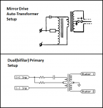
The mirror drive principle is shown in figure 3A:
http://www.htforum.nl/yabbse/index.php?action=dlattach;topic=62043.0;attach=45819;image
A few years ago I (almost) finished my first ESL build. It is a hybrid design consisting of segmented wire frame stators and conventional subwoofer drivers accompanied by a digital crossover. I am very impressed by the results, but the build suffers from some very basic mistakes resulting in some problems. I am now building a second ESL with a better build structure (still segmented wire frame). The step up (1:150) is achieved by 4 toroidal transformers 230v / 2x6v a la Jazzman's build.
I was wondering if it would be possible to expand the build with an auto transformer and capacitor according to the Audiostatic mirrordrive to enhance the bass. The schematics that I've seen of the setup are pretty simple so I thought I might give it a try, however I have hardly any electrical know-how whatsoever so it might aswell be much more difficult than I am assuming.
What are the properties of the auto transformer used in the Audiostatic and can it be obtained a easy as the toroids that I have? What kind of capacitor is needed and how will it's properties have effect on the sound? Furthermore, core saturation is the limiting factor when it comes to low frequencies concerning my toroid transformers; will the addition of the auto transformer prevent their core saturation at low frequencies?
Thanks.
The mirror drive principle is shown in figure 3A:
http://www.htforum.nl/yabbse/index.php?action=dlattach;topic=62043.0;attach=45819;image
Last edited:
In serie of the resistor ( 3,3ohm ) there is a capacitor of 33uF. the capacitor at the top is 25uF.
If the input is 1V ac the output at the top is with 50Hz 0,55V , 60Hz 1V ,70Hz 1,5V
80Hz 1,6V , 90Hz 1,55V 100Hz 1,3V 200Hz 1,05V , measured at the audiostatic es300RS
The output feed with a resistor of 3,3 ohm 2 transformers with the primairy parralel end the secundairy in serie
If the input is 1V ac the output at the top is with 50Hz 0,55V , 60Hz 1V ,70Hz 1,5V
80Hz 1,6V , 90Hz 1,55V 100Hz 1,3V 200Hz 1,05V , measured at the audiostatic es300RS
The output feed with a resistor of 3,3 ohm 2 transformers with the primairy parralel end the secundairy in serie
Thanks for your reply Huibert. As I understand the auto transformer is connected to the primaries of the two step up transformers in parallel. What are the properties of this auto transformer ? Could a commercial 115-230 v auto transformer be used for this purpose ? What if a greater step up ratio would be used ?
Thanks
Thanks
I think the transformer is special built, sowther sells also special transformers ELECTROSTATIC LOUDSPEAKER TRANSFORMERS
The output transformer in the audiostatic is 1: 75 and there are 2 in serie so that gives 1:150 , 1V input 150V output
The output transformer in the audiostatic is 1: 75 and there are 2 in serie so that gives 1:150 , 1V input 150V output
What are the properties of the auto transformer used in the Audiostatic and can it be obtained a easy as the toroids that I have? What kind of capacitor is needed and how will it's properties have effect on the sound? Furthermore, core saturation is the limiting factor when it comes to low frequencies concerning my toroid transformers; will the addition of the auto transformer prevent their core saturation at low frequencies?
The auto transformer for a mirror drive setup can easily be made with a 100VA – 200VA toroidal power transformer that has dual 30V – 40V secondaries. You would connect the two 30V secondaries in series to use as the center tapped auto transformer winding, and not use the 115V primaries at all.
However, driving your 6v/230V toroids with a mirror drive transformer will not prevent core saturation at low frequencies…in fact it will make it worse as the auto transformer would be doubling the input voltage to your toroids at low frequencies.
For your setup with 6V toroidal power transformers, the best idea is probably to use the dual bifilar primaries as their own auto transformer.
This would give step-up of ~150:1 at low frequencies, reducing to ~75:1 at higher frequencies.
Attachment #1: shows the concept I described above with a dual primary single transformer compared with the Mirror Drive setup.
The resistor in series with the capacitor is not part of the mirror drive concept, but should be included to damp the high frequency resonance of transformer and to protect amplifier.
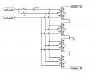
Attachment #2: shows the concept extended to your 4 transformer setup along with some suggested component values to start experimenting with.
As far as component values...in general larger center tap resistor and capacitor values move the start of the boost lower in frequency. However there is a lot of interplay between the transformer inductance, the capacitor value, and the resistor value going to the center tap.
Attachments
Last edited:
Thank you once again Bolserst for a very helpful post. The first ESLs that I constructed wouldn't have seen light without your advice in the past.
The suggestion of using the primary windings as an auto transformer is very appealing. As I've understand from other threads here on this forum, the use of toroids for esl's for bass is only possible when you use many of them, to prevent core saturation. However, disadvantages of using many transformers are worse HF bandwith performance and because of capacitance issues ( please correct me if I am wrong ). Would your suggested setup bypass these problems ? Further along that line: would the use of 8 in total of 6v/230v toroids per esl be possible resulting in a stepup of 150 for higher frequencies and 300 for lower frequencies, without running into high frequency problems and still be able to use low frequency ?
Thanks.
You are correct that using multiple power toroids will limit your HF bandwidth due to winding capacitance.
In my experiments with the Antek toroids, 4 transformers was the limit to avoid limiting HF in the audio band.
If you driving a segmented ESL you might be able to use more than 4, maybe 6 but it would be hard to say without measuring.
What is your D/S spacing and what amplifier are you using?
This will tell us what the stator voltages would be with the different ratios and determine if ionization of air in the gap will occur.
Concerning core saturation:
...more transformers only helps the situation if you are putting the primaries in series.
Since you are putting them in parallel, it doesn't matter how many transformers you use, the LF core saturation will occur at the same input voltage.
You are correct that using multiple power toroids will limit your HF bandwidth due to winding capacitance.
In my experiments with the Antek toroids, 4 transformers was the limit to avoid limiting HF in the audio band.
If you driving a segmented ESL you might be able to use more than 4, maybe 6 but it would be hard to say without measuring.
What is your D/S spacing and what amplifier are you using?
This will tell us what the stator voltages would be with the different ratios and determine if ionization of air in the gap will occur.
D/S spacing will probably be the wire-wire distance which is about 2.2 mm. The amplifier is an NAD 6x30 watt (3x stereo) in which 3 pairs of transformers can be bridged to 3x90 (3x mono) watt. I use tow of the 90 watt amplifiers for the ESL's.
Concerning core saturation:
...more transformers only helps the situation if you are putting the primaries in series.
Since you are putting them in parallel, it doesn't matter how many transformers you use, the LF core saturation will occur at the same input voltage.
So, if I understand correctly, the 4 toroids put in parallel will have the same saturation point as only 1 toroid, which would be around 7 VRMS (for a 6V/230V transfomer ratio) at a frequency of 50 Hz? Phew, I didn't know about that! Should explain why I ruined a 2x50 watt NAD amplifier driving the ESL at a hi pass filter of only 70 Hz. However, the current (above mentioned) amplifier that I use does not fail at this frequency. In fact, it is the quality of the low frequency sound that has been so magical listening to my first ESL's. It is one of the reasons why I now have built new, much larger panels, hoping to be able to get to the lowest crossover reasonably possible.
So if it would be possible to use six 6v/230v toroids (without running in to HF problems), best would be to put some of the primaries in series, for example, 3 pairs, to achieve a reasonable total step up of 38x3 = 1:114, and a core saturation of 2x7 = 14 VRMS at 50 Hz and thus 28 VRMS at 100 Hz? But I might be totally wrong here... 😀
Hi Jeronimo83
you can have increased step up ratio, or increased input voltage, but not both.
If each transformer is has voltage rating 6V: 230V at 50 Hz, then the step-up ratio is about 38 X.
You can assemble a multicore transformer using (say) four transformers, with all of the high voltage windings in series (HV rating rating = 4 X 230V ~1000Vac at 50 Hz)
with the four low voltage winding in series, the input voltage rating is 4 X 6V =24 V @ 50 Hz, and the step up ratio is still 38 X.
With the four low voltage windings in parallel, the voltage rating stays the same, 6V, but the step up ratio is 4 X 38 =152.
You can get a bit of both of you put the four low voltage wings in series-parallel combination - two in series gives double the voltage rating, 12 V. Then put another pair in parallel with thee two - you can have double the step up ratio.
regards
Ok, I just wanted to make sure that the higher step-up ratios you were thinking about wouldn’t damage your panels.D/S spacing will probably be the wire-wire distance which is about 2.2 mm…I use tow of the 90 watt amplifiers for the ESL's.
The large gap and lower power amplifier, you should not run into problems.
Correct. golfnut covered trade-offs between saturation and step-up ratio nicely in his response.So, if I understand correctly, the 4 toroids put in parallel will have the same saturation point as only 1 toroid, which would be around 7 VRMS (for a 6V/230V transfomer ratio) at a frequency of 50 Hz?
I believe you understand the concept.So if it would be possible to use six 6v/230v toroids (without running in to HF problems), best would be to put some of the primaries in series, for example, 3 pairs, to achieve a reasonable total step up of 38x3 = 1:114, and a core saturation of 2x7 = 14 VRMS at 50 Hz and thus 28 VRMS at 100 Hz?
Using 6 of the (230V / 2x6V) transformers you could achieve 28Vrms capability @ 100Hz with 114:1 by:
1) Put the dual 6V windings on each transformer in series, effectively creating six 12v/230v transformer
2) Put all 6 of the series wired transformers from 1) in parallel.
- Each transformer will see the same primary voltage and cores will begin saturating at roughly 28Vrms @ 100Hz.
(the 28Vrms value instead of 2x12 = 24 is based on experience that power transformers operate roughly 10% - 20% below start of core saturation to minimize iron/copper costs)
http://www.diyaudio.com/forums/planars-exotics/186011-diy-bass-transformer-esls.html#post2520512
- Step up ratio will roughly be = 6 x (230/12) = 115
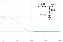
As far as using the mirror drive circuit to boost low frequencies, since you are using a separate power amplifier it would be much better to perform this equalization with a passive line level filter between your preamplifier and amplifier. Something like the attached circuit. The component values shown provide a boost similar to the mirror drive circuit for your NAD amplifier input impedance. Well...it is an "effective" low frequency boost. Being a passive circuit the response equalization is actually done be shelving down the high frequencies.
@golfnut
Note that the transformers jeronimo83 is using have dual 6 volt primaries, so 4 transformers = 8 primaries.
Attachments
Thanks Golfnut and bolsterst for your comments and advice.
From what I had initially read about mirror drive I had understood that the advantages would not only be low frequency boost but also an ability to extend the low frequency range. I understand now that the latter is not so much the case, unless you use very special transformers.
I will try the 6 toroid transformer setup we talked about earlier in my setup, and will report about the results here. Apparently Syb0rg has a similar setup with good results ( KenSeibert.Com Audio Projects , a very helpful description of a full range ESL ).
An alternative to extend the low frequency range might be the use of a seperate bass transformer with better saturation properties for bass a la acoustat. I was thinking about using 40/220v toroid to drive a 220/6600v neon light transformer. This would give me a step up of 5.5 x 30 = 1:165 step up with 40 vrms at 50 hz and 20 vrms at 25 hz saturation. Would a capacitor/ resistor combination as shown in the mirror drive setup in the first post be sufficient to direct the low frequencies to the bass transformers and the high frequencies to the mid/hi transformers? Would it be possible to connect the outputs of both transformers setups in parallel to the stators?
Thanks.
...Would a capacitor/ resistor combination as shown in the mirror drive setup in the first post be sufficient to direct the low frequencies to the bass transformers and the high frequencies to the mid/hi transformers? Would it be possible to connect the outputs of both transformers setups in parallel to the stators?
You will need some type of network to combine the output of the HF and LF transformers to get the desired result.
Without it you would still have problems with core saturation of the HF transformer. How you ask?
the LF transformer would "back-drive" the HF transformer from the secondary side.
The best approach for combining a high step-up ratio LF transformer with a low step-up ratio HF transformer is the Acoustat C-mod circuit.
1) the primary side of the LF transformer is essentially driven full range with a small series resistance to protect amplifier in the unlikely event of core saturation
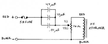
2) the primary side of the HF transformer has 1st order HP filtering to ensure core does not saturate at low frequencies. The filter is made up of the series capacitance (~57uF) and the shunt resistance portion of R1 (~15 ohm). The remaining ~1 ohm of R1 will be in series with the primary to provide the usual damping for the HF resonance. Acoustat used a sliding tap power resistor to provide some adjustment for the damping, but you can use separate resistors for the shunt and series portions.
3) The secondary side of the LF & HF transformers are combined in a "mixer" circuit made from 0.01uF high voltage capacitors and 50Kohm resistors. The bass boost from this circuit and trends for adjustment of component values was posted here:
Acoustat MK121 LF transformer Taps and Mixer Resistors
Attachments
Very informative bolsterst, thanks again. The Acoustat approach looks very sophisticated and I might have a go at it later on when I have assembled my panels. The setup does have some advantages but also introduces some difficulties.
I will try the six toroids in total setup first (mentioned earlier) and see what I come up with with measurements. I will try to extend the bass as low as possible combining a flat response curve, adjusting the panels resonance frequency as a bass boost for the lower frequencies, as you did in your panels (as I read in other posts). This will take a lot of trial and error though, although the many informative posts here on this forum on the subject must give more than some guidance.
Thanks!
- Status
- Not open for further replies.
- Home
- Loudspeakers
- Planars & Exotics
- Audiostatic's "mirror drive": DIY possible?