the problem with thick fat stuff (square or not) is that you don't get enough coverage over the primary windings by the secondary. _-_-bear
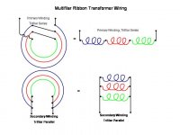
I think a trifilar winding, where three thick low resistance copper magnetic wires are run in parallel to cover a large area when wrapping the core for the secondary with low'ish inductance. Also, trifilar series winding on the primary with thin high resistance copper magnetic wire covers a large area because of the large number of turns. I use this construction techinque for ribbons under 0.1 ohm. Insulated magnetic wire is easy to find.
Unwrapping insulated copper foil inductors is probably the easiest source of tranformer foil for experimentation. For DIY, I would probably use no-glue cloth tape as the insulator and accept spaces between the foil windings
(stolen pictures)
Attachments
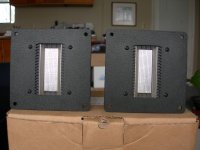
LUST....LUST...LUST..... WIDE RAAL monopole ribbons from DIY swap
I have been DIY'ing 2" high, 1.2" wide dipole ribbons recently in an effort to obtain good vertical dispersion. NdFeB grade N52 magnets are getting cost effective. A clever ribbon suspension is my real technical challenge. I'm willing to give up some high frequency, SPL, and horizontal dispersion for vertical dispersion. I will need to build a step-up transformer, and will use a "slit" amorphous metal toroid from PowerLite and trifilar winding with magnetic wire. I'll post measurements if the vertical dispersion looks good.
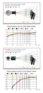
shorter, wider ribbon tweeters look interesting for vertical dispersion.
I have been DIY'ing 2" high, 1.2" wide dipole ribbons recently in an effort to obtain good vertical dispersion. NdFeB grade N52 magnets are getting cost effective. A clever ribbon suspension is my real technical challenge. I'm willing to give up some high frequency, SPL, and horizontal dispersion for vertical dispersion. I will need to build a step-up transformer, and will use a "slit" amorphous metal toroid from PowerLite and trifilar winding with magnetic wire. I'll post measurements if the vertical dispersion looks good.
shorter, wider ribbon tweeters look interesting for vertical dispersion.
Attachments
Oh, well...
that's what you need.
Your stripe resistance is 3 milliOhms.
100W yeilds 180A RMS.
Stripe voltage 0.54
Using decent amorph core with 3 sm sq cross section
like stacked 2xM512/522/612 from magnetec
all you need is 35 turns of magnet wire 1.6 mm in dia.
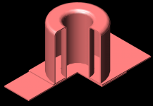
Transformer needs to be balun-like,
see attach. with single turn secondary shown.
Two cores with wound primary stay inside secondary.
Can easliy be done from copper pipes, copper sheet and some soldering")
that's what you need.
Your stripe resistance is 3 milliOhms.
100W yeilds 180A RMS.
Stripe voltage 0.54
Using decent amorph core with 3 sm sq cross section
like stacked 2xM512/522/612 from magnetec
all you need is 35 turns of magnet wire 1.6 mm in dia.
Transformer needs to be balun-like,
see attach. with single turn secondary shown.
Two cores with wound primary stay inside secondary.
Can easliy be done from copper pipes, copper sheet and some soldering
Attachments
someone posted this link in the blowtorch thread
http://focus.ti.com/lit/ml/slup197/slup197.pdf
when I play with some online skin depth calculators I get ~ 1/2 mm for 20 KHz, copper - easily in the thickness range required to get low secondary R in ribbon xfmr depending on geometry
http://focus.ti.com/lit/ml/slup197/slup197.pdf
when I play with some online skin depth calculators I get ~ 1/2 mm for 20 KHz, copper - easily in the thickness range required to get low secondary R in ribbon xfmr depending on geometry
Been doing some calculations,I get 1:50 with 2 turns using the 35v volt winding.
This will land me right around an 8 ohm load for .003 ohm ribbon.
each turn takes 6 inches of coppertape .
The tape dimensions are .0025" x .185".
Using a PCB trace calculator this comes out to .00818 ohm s per turn.
So thinking to start with at least 10 windings to start with.
These are just a few estimations and I will adjust these figures as I start building.
The ribbon for the tweeter will be .5 to 1 mil (depending on what have on hand ) aluminium foil about 3/8" to 1/2" wide with a coragated length of 4" (actual length will be some where between 6" to 8" ).
between 4 10mm x 10mm x 40mm magnets found ACO (ace hardware) with a 1/2" gap. jer
Dimensions will found experimently.
Skin depth is useful when you know exact field distribution, terminals included.someone posted this link in the blowtorch thread
http://focus.ti.com/lit/ml/slup197/slup197.pdf
when I play with some online skin depth calculators I get ~ 1/2 mm for 20 KHz, copper - easily in the thickness range required to get low secondary R in ribbon xfmr depending on geometry
Thicker/thinner foil would/would not hurt "depending on geometry"
BTW, in terms of impedance you can't beat balun/cable transformer... otherwise ham radio guys would not use them.
the Dixon paper is pretty clear on the winding loss increase with skin effect, my crude guesstimate is that you can easily be looking at ~1dB response droop at 20KHz in a ribbon xfmr from this effect
remember that RF is working at many 10's of Ohms impedance in transmission lines, the ribbon is ~45 milli-Ohm for the dimensions given - at 1000x lower than RF typical "50 Ohm" lines/loads the skin effect become significant at much lower frequencies - including high audio frequencies
I doubt even 1 dB skin effect/eddy current caused droop would be audible but it is measurable and getting near audibility thresholds - something to consider/calculate in the xfmr design
and again there is no reason to design for 100+W the RAAL numbers are "puffery" - the ribbon will burst into flame at with that power density - just look at an electric stove top or space heater element that visibly glows red with heat - and calculate the surface area/power ratio
Last edited:
0.006cm=0.06mm by width 10mm yeilds 0.6 mm^2, fusing current 65A by Preece
(I = 12277*A^.75*A, amps and sq in)
Peak power might of been implied by topic starter (100-200W).
I've achieved kiloamp range secondary current with such design even @ frequencies well above audible range.
(I = 12277*A^.75*A, amps and sq in)
Peak power might of been implied by topic starter (100-200W).
I've achieved kiloamp range secondary current with such design even @ frequencies well above audible range.
I was assuming the miss-typed thickness dimension was 0.006 mm - in line with foil dimensions from other ribbon tweeters
http://www.diyaudio.com/forums/gtse...s-exotics/81162-looking-ribbon-foil.html#1170
http://www.diyaudio.com/forums/gtse...s-exotics/81162-looking-ribbon-foil.html#1170
Last edited:
direct drive is woefully inefficient - many audio output transistor's Vsat is bigger than the Vdrop on such a low R load - but yes handling the current itself isn't too hard
often people want to put he ribbon in a box with a passive XO so it needs a xfmr to be a fairly close match the other driver's impedance
often people want to put he ribbon in a box with a passive XO so it needs a xfmr to be a fairly close match the other driver's impedance
Last edited:
That is a very intresting paper, however I have not read it compleatly to understand all of it yet as some of it seems contridictory.
It also mostly focuses on muliple secondary layers that 100% overlapped.
I am planning on using only one layer with no more than 10% or 20 % total overlap if that.
Although I was thinking of using two or three layers per winding to further lower the DCR.
The paper suggest this is not a good idea.
But, it also goes goes onto say that the effect is less prominit when the conductor Is thinner than the skin effect itself.
In this case the skin effect is .5 mm at 20 khz.
My copper foil has a thickness 2.5 mil or .064 mm well below the suggested safe area even when using 3 or 4 layers.
Your right, I would not suggested applying 100 watts into a 4" ribbon that was just a ball park figure to start some calculations with an average amplifier power since most 50 watt amps can't supply enough curent into even a 2 ohm load (I do not wish to argue this point).
For instance it takes every bit of power my crown DC300A can muster up to make my Appoge duetta ribbons (tweeters) to play at a decent level but is nowhere the 110db level I would like them to be at.
I have read of people running as much 800 watts rms on them, above this your asking for trouble and many have popped them like a fast blow fuse.
But I have never seen a published figure of exactly how much current they can actualy handle.
IMO, even if there was a 1db drop due to the skin effect this would not be as bad as having a secondary DCR the same or even half that of ribbon it self.
Also the paper is based on High Frequencies which is any frequency above 1mhz.
Another paper that I read on switch mode supplies suggest that the losses from the skin effect start to become an issue at frequencies of 100 khz and above.
Well, a 100 khz square wave has many harmonics well into and above the 1mhz range.
I'm not questioning the measure ablity of the losses due to the skin effect.
But I don't think it will be as much of a factor compared to a high secondary DCR and leakage inductance and not to mention transformer interwinding capacitance.
Granted 20 khz is the design limit for audio, But, can one actualy tell the difference between 20 khz sine wave and a 20 khz square wave ,much less ,at only a 1 db drop at +90db spl while listening to music? jer
p.s. just a few things to consider.
Last edited:
I'm ready to start building this thing!
So far I am contemplating at least 10 2turn windings each with two layers of copper foil 12" long , .1875" wide and a 2.5mil foil thickness to start with.
This would give me a 25:1 ratio.
This may warrant the need for second layer as have found with a test winding that I may not have compleat coverage of the core.
Acording to the ANSI PCB TRACE CALCULATOR each strip (winding) will have a resistance of .020 ohms and other calculators report .01636 ohms.
This is pretty close to each other so I will asume the worst one of .02 ohms to compensate for any other losses in output busbar and solder resistances and hope it will be less.
Also the calculator tells me that the strips have .6 watt loss with 10deg c rise in temperature and a .1v drop at 5.725 amps of current.
multiply (or divide where applicable) by 20 windings in parallel these figures are starting to look impressive.
Except the DCR is only around .001 ohms which may also warrant a second layer and/or 4 strips instead of 2 per winding.
Whew,that alot of windings!
My roll of copper tape is 36 yards long and only cost me $7.00.
So, material supply is not an issue except that if it works good I would like to have enough tape to build two for stereo with out having to travel 50 miles to get some more.
Any more thoughts or suggestion on this? jer
I have been extensively researching PCB trace calculators and they are all about the same pretty much.
Except the one from clemson university.
It also calculates a.c resistance as well as d.c. resistance.
It suggests that a.c resistance is about double that of the d.c. resistance at 20mhz and no change from 20khz to 2mhz.
I didn't spend the time to find the frequency where the a.c. resistance begins to rise.
Another neat thing about about the calculator is that it allows you to change material type.
Really cool?
It suggests that an aluminium strip .5mil thick .45" wide X 8" long has a resistance of .039 ohms.
Suddenly the .001 ohm resistance of the transformer doesn't look so bad after all. jer
p.s I had made a mistake in post 57.
It should state that 2 turns would be a 50:1 ratio and 4 turns would give a 25:1 ratio and so on.
Sorry about the confusion.
So 8 turns would be a 12.5:1 ratio and this would put my load impedence in the 6 ohm range using the data presented.
Sweet! jer
Last edited:
- Status
- This old topic is closed. If you want to reopen this topic, contact a moderator using the "Report Post" button.
- Home
- Loudspeakers
- Planars & Exotics
- How to make a good transformer for ribbon tweeter?