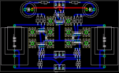
Kari,
It remains one problem on your last design, if you want to replace the central or left mosfet ; you have to remove the two others and heatsinks to do that ; a best way would be to give better access to each mosfet to be able to replace them... {I have changed twice since installation}
Otherwise its a good design.
Regards.
Alain.
Kari,
I have used this sort of design for my first prototype, but as soon as I
had need to replace one of the mosfet specialy the balanced pair, I was in trouble ; even to access the screw it's difficult... and to reinstall the new mosfet even harder...
You could find a way to arrange the diff pair to be more accessible:
by changing the heatsinks or with a little move ...
put the diff mosfet pair lying flat on the circuits board...
moved them to the lower part, so you can place a hole {in the other heatsink} to access the screw...
place the CCS under the pcb...
Better use a pref board and have a try, I think you will see what happens.
Regards.
Alain.
Thx for your thoughts. Still i think if you lift the heatsink with the fet still attached to it, this should not be a problem.
I could ofcourse turn the fets 90degress and move the ccs down but then the board size is going to get a lot bigger. I'll play around with some ideas on a protoboard, but as it is know i'm not going to change the layout.
Thx,
Kari
I could ofcourse turn the fets 90degress and move the ccs down but then the board size is going to get a lot bigger. I'll play around with some ideas on a protoboard, but as it is know i'm not going to change the layout.
Thx,
Kari
I dont see that as a big problem. You can unsolder the hole unit including the heatsink and pull it out, mount the new mosfet and solder the unit back in, or am I missing something there?It remains one problem on your last design, if you want to replace the central or left mosfet ; you have to remove the two others and heatsinks to do that ; a best way would be to give better access to each mosfet to be able to replace them... {I have changed twice since installation}
The issue is propably the alignment of the fet?
But ofcourse, it would be easier to be able to access the Fets directly.
Just out of curiosity, what happened to the fets you changed? I didn't manage to fry any yet.
To get another thing clear, I guess the diff pair needs matching, right?
Steen
steenoe,
I have changed about 4 pairs, even matched at 0.01 volts
there are sensible differences...
Starting with series of matched MosFets IRF 610 same lot code
and same 0.01 volts values there are sonic differences
so I have unsoldered them a lot of times... and installed the heatsinks
with screws not with solder to go quicker!
I am just trying to help here.
A+
Alain.
I am aware of that, Alain. If my post sounded otherwise, I am sorryI am just trying to help here.
Thanks a lot for the info on the diff pair. I guess I will have to obtain a tube of 610's and match them.
Steen
steenoe,
Better buy 25 minimum, if you match them within 0,01 volts
there are differences in transconductance between the pairs
that you choose ; have fun.
For my part I bought a tube of 50 since the A75 and used the unmatched for tests prototypes, for CCS's etc.
If you can get series of 4 to 6 well matched it's fun to change only one
in the diff pair to get best sonic pairs!!!
{also have same gain, in the right and left side of the diff. pair}
I didn't blow any of them, but some already used and not of higher sonic
quality have been trashed.
The protos have worked in the 60 to 125 degree range, depending of the
CCS negative voltage ; and with bias as high as 80/100mA each...
Regards.
Alain.
Alain, from this I understand you go to the extremes to get the best soundIf you can get series of 4 to 6 well matched it's fun to change only one
I am not confident, that I could do something like that anyway

Steen
question on input/output locations on bosoz pcb
I noticed on Kari's bosoz pcb that the input and output traces
are close to together because the holes for the input and output
leads are near each other. Will this cause any problems with
feedback oscillations? Shouldn't they be further apart?
One reason why I ask is that when I recently built my aleph 5
I had some distortion because my input and output leads
were too close.
John
It shoudn't be a problem.
What about the idea of adding cascoding as metalman did? This could be done
pretty easily and if you dont want to "cascode" you'd simply bypass it with a jumpwire.
Any thoughts?
The boards are 99% ready, i just need to do some final cosmetic work to the silkscreen.
What about the idea of adding cascoding as metalman did? This could be done
pretty easily and if you dont want to "cascode" you'd simply bypass it with a jumpwire.
Any thoughts?
The boards are 99% ready, i just need to do some final cosmetic work to the silkscreen.
Have been watching this thread without comment
But now I have to jump in to say
very nice job!
it could also be made single layer (with only two jumpers)
could you post a schematic ?
I might consider trying a proto using printer transfer film.
but ha who am I kidding I allready have an aleph 30 , a
1541 dac and a TQMT speaker project all underway.
Kari said:The only downside beeing that the board is rather big, 170mm x 100mm. Also i'm going to use the toplayer as a ground plane.
We'll go with the cascoded board, right?
/Kari
Whatever you think is the best way to go Kari.
Anthony
Hmm, sorry to ask, what are the advantages of cascoding, compared to the original board?We'll go with the cascoded board, right?
Steen.
Update:
While my mother in law desided to come for a visit i desided to go for a business trip so i haven't updated the board until now.
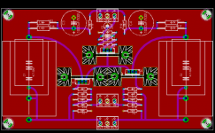
I still need to figure out the advantages of cascoding so i'm going forward with the design i started with. The sinks are now turned 90degress, i've added a 22uf cap to reduce noise from the zener and added a groundplane on the toplayer.
I'll have a look at the pwrsupply this weekend too.
I should get some estimates on pricing beginning of next week.
/Kari
Attachments
Sounds great, KariI should get some estimates on pricing beginning of next week.
You are hereby legaly excusedWhile my mother in law desided to come for a visit i desided to go for a business trip
Does anyone have anything to say about this subject please tune inI still need to figure out the advantages of cascoding
Steen
- Status
- This old topic is closed. If you want to reopen this topic, contact a moderator using the "Report Post" button.
- Home
- Amplifiers
- Pass Labs
- Heatsinks for Bosoz?

