mbrennwa, Here are my inductance versus frequency measurements for the Hammond 159ZC. I did some internet research to figure out a way to measure the inductance.
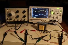
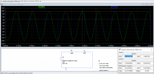
I set up a simple circuit with a 3.06 50kOhm resistor in series with the 159ZC and connected it to a HP 3310A function generator (output impedance 50R). Oscilloscope probes were placed at the function generator ouput and at the input to the choke, to measure the overall voltage output from the function generator and the voltage drop across the choke. The voltage drop across the resistor was calculated using the measured voltages. The input voltages were sine waves of various frequencies. These measurements were used to calculate the choke inductance.
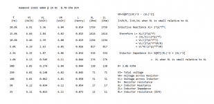
I have tabulated the measurements and results of my calculations. The results showed inductance decreased with with frequency. By 20kHz, the inductance was very low.
I'm not an electrical engineer, I don't know the theory, so I did some internet searching to find information on inductance and frequency response of an inductor loaded amplification output stage. I didn't find any specific information but I did find more theory on inductors and their properties. So I read some more and decided to calculate the AC impedance of the Hammond at the various frequencies. That showed impedance increased as frequency increased.
So from what I can see, it is the impedance of the choke that is the property that directly affects the amplifier's frequency response. At low frequencies, the inductor impedance is low, so the output level of the amplifier is reduced. As the frequency rises and impedance rises, there is a point where the impedance is high enough that the output level is no longer reduced. At that point further increase in impedance no longer has a noticeable effect on output level.
So that is my non-professional, hobbyist electronics diyer's take on choke inductance and amplifier frequency response.
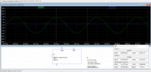
I also did a couple of LTSpice simulations of the measurement setup. LTSpice modelling did not seem to adjust the inductance with frequency change so I manually changed the inductance when I changed the frequency. The simulated AC voltages were in line with the measured voltages. Measured voltages were Vrms and LTSpice voltages were Vp.
Some pertinent reading:
https://www.electronics-tutorials.ws/accircuits/ac-inductance.html
https://www.electronics-tutorials.ws/inductor/ac-inductors.html
RL Series Circuit - LEKULE
I set up a simple circuit with a 3.06 50kOhm resistor in series with the 159ZC and connected it to a HP 3310A function generator (output impedance 50R). Oscilloscope probes were placed at the function generator ouput and at the input to the choke, to measure the overall voltage output from the function generator and the voltage drop across the choke. The voltage drop across the resistor was calculated using the measured voltages. The input voltages were sine waves of various frequencies. These measurements were used to calculate the choke inductance.
I have tabulated the measurements and results of my calculations. The results showed inductance decreased with with frequency. By 20kHz, the inductance was very low.
I'm not an electrical engineer, I don't know the theory, so I did some internet searching to find information on inductance and frequency response of an inductor loaded amplification output stage. I didn't find any specific information but I did find more theory on inductors and their properties. So I read some more and decided to calculate the AC impedance of the Hammond at the various frequencies. That showed impedance increased as frequency increased.
So from what I can see, it is the impedance of the choke that is the property that directly affects the amplifier's frequency response. At low frequencies, the inductor impedance is low, so the output level of the amplifier is reduced. As the frequency rises and impedance rises, there is a point where the impedance is high enough that the output level is no longer reduced. At that point further increase in impedance no longer has a noticeable effect on output level.
So that is my non-professional, hobbyist electronics diyer's take on choke inductance and amplifier frequency response.
I also did a couple of LTSpice simulations of the measurement setup. LTSpice modelling did not seem to adjust the inductance with frequency change so I manually changed the inductance when I changed the frequency. The simulated AC voltages were in line with the measured voltages. Measured voltages were Vrms and LTSpice voltages were Vp.
Some pertinent reading:
https://www.electronics-tutorials.ws/accircuits/ac-inductance.html
https://www.electronics-tutorials.ws/inductor/ac-inductors.html
RL Series Circuit - LEKULE
Attachments
I finally finished the left channel so the amplifier is complete. I listened to it for a couple of days and it sounded good, as good as my other single ended SIT follower amplifiers. I don't think I can blindly distinguish between any of my single ended SIT amplifiers, even though they have a variety of output power levels. With my highly sensitive speakers, amplifier power is not an issue, especially since I don't listen at ear damaging and neigbour offending levels. I evaluate sound systems by how I feel when listening, and I felt happy when I listened to this amplifier in my system. The music entertained me, and I had no negative thoughts of how the music was presented. So that meant I really liked the ampliifer. Of course the rest of my system contributed to the overall sound. So that is my simplistic evaluation. I don't try to do a detailed analysis of bass, treble, soundstage, air, separation, etc, that many audiophiles do.
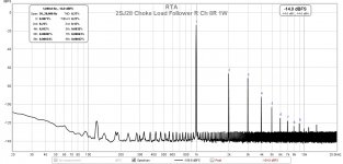
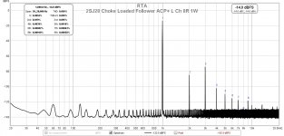
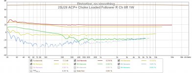
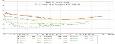
However I did some measurements to confirm that the amplifier is working as it should. I had made and posted some measurements of the right channel previously. Here are some measurements of the left channel and the same measurements of the right channel for comparison. This time I used my Focusrite 2i2 (Gen 2) and REW software to generate a signal from 20Hz to 40kHz to measure the frequency response and harmonic distortion. My ACP+ was used to amplify the generated signal in order attain the 8R 1W output at the amplifier. The 2SJ28 has low transconductance, with 3.79Vrms input for the amplifier to output 2.83Vrms.
The 2SJ28 in both channels were quite closely matched for Vgs. At Vds=21.0V and Iq=1.5A, left channel Vgs=5.84V and right channel Vgs=5.76V. As can be seen in the distortion plots, the left channel and right channel H2 distortion levels were quite quite different. The left channel H2 was much lower, resulting in the left channel being H3 dominant. But with the distortion levels being lower as a follower than if the amplifier was common source, the voltage gain stage/preamp can shape the sound. If the voltage gain stage/preamp has higher distortion and is H2 dominant, then the resultant output may be H2 dominant. That is the case with my Luminaria preamp providing voltage gain, and I will post measurements of the Luminaria/2SJ28 Follower left channel later.
All in all, I am quite happy with this amplifier. It has not many parts, uses First Watt amplifier power supply voltage (unipolar so a bipolar supply can be split into separate left and right channels) so an existing power supply can be re-used, uses a not too expensive Hammond choke for loading, and dissipates only about 35W per channel of heat at idle. And it has the great VFET/SIT sound!
Any by the way, I used 2SJ28 VFETs because that is what I had, but 2SK82 VFETs can also be used. The power supplies just need reversing and correct polarities observed.
Attachments
-
 2SJ28 choke load follower ACP+ R Ch 8R 1W.jpg141.4 KB · Views: 151
 -
 2SJ28 choke load follower ACP+ L Ch 8R 1W.jpg143.5 KB · Views: 157
 -
 2SJ28 choke load follower ACP+ R Ch 8R 1W Sweep.jpg143.1 KB · Views: 149
 -
 2SJ28 choke load follower ACP+ L Ch 8R 1W Sweep.jpg146 KB · Views: 208
 -
 2SJ28 Choke Load Follower.jpg571.7 KB · Views: 223
 -
 2SJ28 Choke Load Follower and Luminaria.jpg411.7 KB · Views: 184
All in all, I am quite happy with this amplifier.
Awesome. I truly enjoy reading the saga of your builds from beginning to end. I learn quite a bit and I usually wind up copying and pasting quite a bit into my own journals to come back to and build further understanding.
Thanks!

The 2SJ28 has low transconductance, with 3.79Vrms input for the amplifier to output 2.83Vrms.
This is the only thing that I could not quite wrap my wee brain around. Am I misinterpreting, and/or does the 'amplifier' actually attenuate and have a gain of <1. I clearly have a bit of a gap here. A teaser of a hint may get me started in the right direction. For now, I'm newb-level stumped.
")
Patrick,
If my understanding is correct, this is a common drain amplifier, so its voltage gain is <1.
Common drain - Wikipedia
With low transconductance the voltage gain doesn't get as close to the asymptotic value of 1.
If my understanding is correct, this is a common drain amplifier, so its voltage gain is <1.
Common drain - Wikipedia
With low transconductance the voltage gain doesn't get as close to the asymptotic value of 1.
Thank you all for your comments.
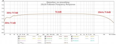
ra7, Here is a zoomed-in version of the frequency response. There is a bit of sag in the frequency response but I can live with it. The Hammond 159ZC is considerably less expensive and lighter weight than the 193V.
Patrick, It's what Dennis said. The amplifier is a source follower, also known as common drain. The drain is ground and the output signal is taken at the source. There is no voltage amplification and depending on the device there may be considerable negative gain. The advantages are lower output impedance and lower distortion.
The latest diyAudio VFET amplifiers are also common drain. The difference is that they are CCS loaded and this amplifier is choke loaded. Choke load allows for lower power supply voltage and less heat sinking as the choke drops much less voltage and dissipates much less energy than a CCS. The diyAudio VFET amplifiers have a built-in voltage gain stage at their input whereas I am using my Luminaria preamp for voltage gain.
Attachments
Hi Ben,
Thank you so much for sharing this with us.
I'm curious if you might have any thoughts about why one channel is H2 while the other is H3 dominant. I noticed also the H2 dominant one has lower distortion below 100Hz. Could some variations between the chokes cause this?
Thanks,
Dennis
Thank you so much for sharing this with us.
I'm curious if you might have any thoughts about why one channel is H2 while the other is H3 dominant. I noticed also the H2 dominant one has lower distortion below 100Hz. Could some variations between the chokes cause this?
Thanks,
Dennis
Hi Dennis,
I don't know for sure but I suspect that it is due to large variations in the characteristics of the individual VFETs. When I had these VFETs in a 193V loaded common source L'Amp, one channel had lower H2 than the other, although it was still H2 dominant until near maximum power output when H3 became dominant. The other channel was H2 dominant at maximum power output.
However, in common drain, the distortion levels are much lower so when combined with the Luminaria for voltage gain, the output was H2 dominant as the Luminaria distortion profile dominanted. I will post the distortion plots later today.
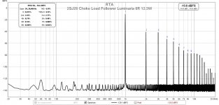
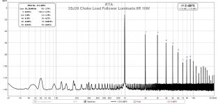
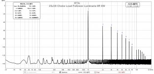
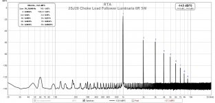
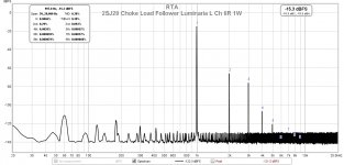
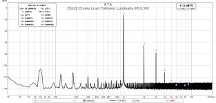
Here are the distortion plots for the recently completed left channel with a standalone 1kHz oscillator providing the signal and the Luminaria preamp providing the voltage gain. As can be seen, the amplifier output was H2 dominant. The Luminaria's distortion dominated over the 2SJ28 follower's distortion.
For comparison the right channel with Luminaria providing voltage gain distortion plots are here:
Sony VFET 2SJ28 Single Ended Choke Loaded Follower Amplifier
The ACP+ does not have enough voltage output to drive the VFET follower to maximum power output.
For comparison the right channel with Luminaria providing voltage gain distortion plots are here:
Sony VFET 2SJ28 Single Ended Choke Loaded Follower Amplifier
The ACP+ does not have enough voltage output to drive the VFET follower to maximum power output.
Attachments
-
 2SJ28 Choke load follower Luminaria L Ch 8R 12.5W.jpg146.6 KB · Views: 72
 -
 2SJ28 Choke load follower Luminaria L Ch 8R 10W.jpg145.6 KB · Views: 81
 -
 2SJ28 Choke load follower Luminaria L Ch 8R 8W.jpg143.9 KB · Views: 164
 -
 2SJ28 Choke load follower Luminaria L Ch 8R 5W.jpg142.8 KB · Views: 160
 -
 2SJ28 Choke load follower Luminaria L Ch 8R 1W.jpg145.5 KB · Views: 170
 -
 2SJ28 Choke load follower Luminaria L Ch 8R 0.5W.jpg145.5 KB · Views: 173
Patrick,
If my understanding is correct, this is a common drain amplifier, so its voltage gain is <1.
Common drain - Wikipedia
With low transconductance the voltage gain doesn't get as close to the asymptotic value of 1.
Thank you, Dennis! That got me started in the right direction of understanding. Still more reading and understanding to follow on my part.
Thank you all for your comments.
Patrick, It's what Dennis said. The amplifier is a source follower, also known as common drain. The drain is ground and the output signal is taken at the source. There is no voltage amplification and depending on the device there may be considerable negative gain. The advantages are lower output impedance and lower distortion.
The latest diyAudio VFET amplifiers are also common drain. The difference is that they are CCS loaded and this amplifier is choke loaded. Choke load allows for lower power supply voltage and less heat sinking as the choke drops much less voltage and dissipates much less energy than a CCS. The diyAudio VFET amplifiers have a built-in voltage gain stage at their input whereas I am using my Luminaria preamp for voltage gain.
Thank you, Ben! I need to consider a design potentially similar. I really only 'need' about 3Wrms to get to more than comfortable listening levels. Between most of my pre-amps and power amps, I have too much gain. With rare exception, I use what may be considered too much attenuation and 'throw away' gain. The exception may be a few pre-amps with the F4.
More food for thought. Thanks again for sharing!
Edited to add: It may work very well in my case b/c I am using 4ohm speakers. I can get away with less voltage gain than those with higher impedance speakers.
Patrick,
It sounds like a follower amplifier is a great fit for you system. Your F4 is a push-pull follower with no voltage gain stage so that is why your high gain preamps work well with it.
You definitely should try some single ended follower amplifiers. They don't have many parts and are simple to build. One very popular follower is the MoFo. Or if you have some SITs, whether VFETs or Tokins, you can build a SIT follower. Although the Tokins can handle higher voltage and current, many have built them with lower voltage and current.
If you have a preamp with low output impedance, say less than 100 Ohm, you can get by with no input buffer too. That is why my diy amplifiers do not have input buffers.
So a follower amplifier with no voltage gain stage and no input buffer is a simple circuit with low parts count that can be easily built point to point. And if you have a bipolar First Watt type of power supply, it can be easily modified to two channels of 24V supply to power each channel separately.
Although the 2SJ28 is a P channel VFET, this circuit can be easily adapted to N channel devices. It's just a matter of reversing voltages and polarities.
Patrick,
If you have a diyAudio SE VFET amplifier, then you already have a VFET follower amplifier. As I mentioned previously, the difference between the diyAudio amplifier and my amplifier is that the diyAudio amplifier is CCS loaded and my amplifier is choke loaded, the diyAudio amplifier has an input buffer and a transformer for voltage gain and my amplifier has neither.
If your preamp has a lot of gain and high voltage output, you can disconnect the amplifier buffer/voltage gain stage and send your preamp output directly to the VFET output stage. Connect the preamp output positive to D+ on the output stage board and the preamp output ground to Ground on the output stage board.
Then you won't throw away gain, you will eliminate a possibly unnecessary stage, and you may get better sound.
Hi Ben,
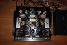
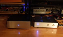
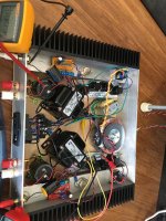
Here’s my 2sj28 follower build.

I was tripped up in the build with the high gate bias voltage requirement. Had to buy a smaller power trafo and then add a second trafo for the bias supply. Anyway, it is very stable at 1.5A bias. A mess of wires right now and things are not bolted down, but very little hum and sounds amazing with my SCG pre.
What are you doing about turn on thump? I studied the output and it hits about 18V at turn on and slowly climbs down to 0V over a minute as the output cap charges up. Too slow for my liking. Have you tried a relay or something else?
Also, a broader question about mounting the VFETs. I used a keratherm-like mounting pad and no goop. Is that enough? It never goes above 40C on the VFET body itself. What is your experience? Maybe "the one and only" can chime in as well as others.
Here’s my 2sj28 follower build.
I was tripped up in the build with the high gate bias voltage requirement. Had to buy a smaller power trafo and then add a second trafo for the bias supply. Anyway, it is very stable at 1.5A bias. A mess of wires right now and things are not bolted down, but very little hum and sounds amazing with my SCG pre.
What are you doing about turn on thump? I studied the output and it hits about 18V at turn on and slowly climbs down to 0V over a minute as the output cap charges up. Too slow for my liking. Have you tried a relay or something else?
Also, a broader question about mounting the VFETs. I used a keratherm-like mounting pad and no goop. Is that enough? It never goes above 40C on the VFET body itself. What is your experience? Maybe "the one and only" can chime in as well as others.
Attachments
Last edited:
- Home
- Amplifiers
- Pass Labs
- Sony VFET 2SJ28 Single Ended Choke Loaded Follower Amplifier