if JFets , input LTP max iq is 10mA
so , yeah - without checking resulting current through LTP with your resitor , yeah
just check that resulting current from upper mos CCS is 10mA, (9V1-4V) /R
so , yeah - without checking resulting current through LTP with your resitor , yeah
just check that resulting current from upper mos CCS is 10mA, (9V1-4V) /R
Pass DIY Addict
Joined 2000
Paid Member
The jFets will be a bit more linear, with a pinch more treble. The 9610 will be a bit more "lush" with more mids and a pinch less treble.
I would also recommend mounting Q6 directly to your main sink, on the Q2/Q11 side. Since those transistors will heat up before the other side will, your relative offset will stabilize more quickly.
I would also recommend mounting Q6 directly to your main sink, on the Q2/Q11 side. Since those transistors will heat up before the other side will, your relative offset will stabilize more quickly.
Guys, thanks for the help!
Eric, that's a pretty accurate description of what I'm getting now.
I like it, but not crazy about the resolution and treble region.
I may also switch out the IRFP044n for the IRFP140.
Any other output stage mosfet I should consider, maybe a IRFP150?
Thanks,
Vince
Eric, that's a pretty accurate description of what I'm getting now.
I like it, but not crazy about the resolution and treble region.
I may also switch out the IRFP044n for the IRFP140.
Any other output stage mosfet I should consider, maybe a IRFP150?
Thanks,
Vince
no need to worry too much - with so few mosfets in output and with NFB to keep things up
though , 150 are fave of mine ....... as known, practically 2pcs of 240 in one case, even if 2 pcs of 240 can endure more heat than one 150
though , 150 are fave of mine ....... as known, practically 2pcs of 240 in one case, even if 2 pcs of 240 can endure more heat than one 150
Thanks ZM.
Would be a sin to change too many things at once anyway. 😀
I may go a little bonkers and convert it into mono-blocks. It's already dual-mono.
I had to dial back the bias a little which I feel is affecting the sound.
I may also be a little chicken because I can hold hand on heat sink for 5 to 10 seconds while being very uncomfortable. Smart thing to do is measure all temps before going overboard.
BTW- I put heat sinks on all IRF9160.
Thanks again!
Last edited:
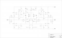
ZM, does R24 set the current delivered to the LTP or is R24 there to bias Q1?
Perhaps R24 is there to do both?
I think it's almost 11mA by using R24, 475 Ohms in equation (9V1-4V) /R.
Do R24, R26 and V2 form a voltage divider to set DC offset?
I know V2 tweaks DC offset, but I'm trying to understand the relationship between the parts.
thx!
Perhaps R24 is there to do both?
I think it's almost 11mA by using R24, 475 Ohms in equation (9V1-4V) /R.
Do R24, R26 and V2 form a voltage divider to set DC offset?
I know V2 tweaks DC offset, but I'm trying to understand the relationship between the parts.
thx!
Think of it like this:
The Aleph current sources up top (Q1 and Q10) deliver a current to the output as set by R11 and R33. Say a positive 1A from the positive supply to the output node. If the output stage (Q2 and Q11) is fully turned off, the current from the current source will try to flow though the load, and the output voltage will the to go up.
The more the output fets Q2 and Q11 are turned on, the more current will get sinked to the negative supply (or the more negative current will flow to the output node from the bottom up). If the current through the current source and the current though the output stage are equal, the output node will sit at 0V, right in the middle between the supply voltages.
Q2 and Q11 get turned on according to their respective gate voltages. The gate voltages are set by the voltage developing over the resistors R23 and R25 and are thus dependent on the current that's pushed through them. This current is set by R24, R26 and V2. So by adjusting the current through the LTP, you're matching the output stage current sinking to the Aleph current source delivery, and therefore the output offset.
Thanks Rodeodave. My question was more geared toward how the supporting components around Q6 CCS and LTP Q5 and Q7 setup the semiconductors operation. I'd like to replace the LTP mosfets with jfets safely since the jfets are tiny little jewels. 🙂
Post 3281 above has the schematic I'm using, filled in with resistors changes to reduce current delivery to the LTP. Perhaps the former is not a proper expression, but that's all part of my problem.
Thx!
Post 3281 above has the schematic I'm using, filled in with resistors changes to reduce current delivery to the LTP. Perhaps the former is not a proper expression, but that's all part of my problem.
Thx!
Hi vdi_nenna, There is a PDF attached to post 371 over here: Babbelfish J PCBs that may be of interest, non x version.
Andy
Andy
Thx, I went over it a couple times before.
This CCS is a little simpler, but I'm still unsure of a couple things.
This CCS is a little simpler, but I'm still unsure of a couple things.

- Home
- Amplifiers
- Pass Labs
- The Aleph-X