There are going to be some lucky folks come April 8th. 😉 😉 (I’m a greedy boi, what can i say). On a similar note I received a pair Japanese SITs the other day surprisingly fast after ordering. I look forward to some future projects. Though my wife is probably wondering what im doing with all of these audio system components stacking up around the place.
high current SMPS filter // after the ~ 200 VFET kits are gone
Of course, nobody who is lucky enough to win the buyer's lottery and obtain one of these amps, would ever think about changing any aspect of Nelson's design. You use his circuits, his boards, his specified part-numbers, and you even wire the chassis using the same colors of insulated wire as he drew on page 11 of the pdf manual. When Picasso says "paint this Cadmium Yellow," you don't argue, you go buy Cadmium Yellow paint and you follow his instructions.
However, after those approx. 200 amp kits are sold and built and installed, the post-VFET versions will thrive and multiply. Builders with lots of chutzpah & bravery will no doubt add embellishments, accessories, and features not present in the original NP VFET design.
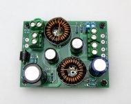
One such possibility, still just a prototype, is shown below. It's a four pole lowpass filter, which replaces Nelson's two pole filter shown on page 6 of the pdf manual. The goal of this PCB is to remove even greater amounts of hash, crud, noise, ick, and general HF unpleasantness from the SMPS output, providing an even cleaner DC supply to the amp. As you can see for yourself if you look up the inductor part number -- clearly visible in the stunning photographs taken by wizard 6L6 -- the components themselves are good for about 9 amperes of DC current. Each VFET channel draws less than 2 amps, and my wet-finger-in-the-breeze guess is that future non-VFET channels will draw less than 3 or 3.5 amps. So there's a nice margin of safety. When you order PCBs from fab, should you specify double-thick (2 oz) copper? Oh yes.
I'm still testing the board and performing experiments. It may not pass the tests, the experiments may fail, and this board may never get released. But, fingers crossed, so far so good.
The top side silkscreen says "6A maximum" because I've provided flexible PCB footprints that accommodate several different inductor part-numbers. Expecting the inevitable backorder / out of stock / we don't have Mouser in my country / kinds of difficulties. The highest current inductor that fits, is rated 9.8 amperes. The substitutes that fit, have lower current ratings, including one rated for "only" 6A. The top silkscreen makes the conservative worst-case assumption that the builder has been forced to purchase the scrawniest inductor.
_
Of course, nobody who is lucky enough to win the buyer's lottery and obtain one of these amps, would ever think about changing any aspect of Nelson's design. You use his circuits, his boards, his specified part-numbers, and you even wire the chassis using the same colors of insulated wire as he drew on page 11 of the pdf manual. When Picasso says "paint this Cadmium Yellow," you don't argue, you go buy Cadmium Yellow paint and you follow his instructions.
However, after those approx. 200 amp kits are sold and built and installed, the post-VFET versions will thrive and multiply. Builders with lots of chutzpah & bravery will no doubt add embellishments, accessories, and features not present in the original NP VFET design.
One such possibility, still just a prototype, is shown below. It's a four pole lowpass filter, which replaces Nelson's two pole filter shown on page 6 of the pdf manual. The goal of this PCB is to remove even greater amounts of hash, crud, noise, ick, and general HF unpleasantness from the SMPS output, providing an even cleaner DC supply to the amp. As you can see for yourself if you look up the inductor part number -- clearly visible in the stunning photographs taken by wizard 6L6 -- the components themselves are good for about 9 amperes of DC current. Each VFET channel draws less than 2 amps, and my wet-finger-in-the-breeze guess is that future non-VFET channels will draw less than 3 or 3.5 amps. So there's a nice margin of safety. When you order PCBs from fab, should you specify double-thick (2 oz) copper? Oh yes.
I'm still testing the board and performing experiments. It may not pass the tests, the experiments may fail, and this board may never get released. But, fingers crossed, so far so good.
The top side silkscreen says "6A maximum" because I've provided flexible PCB footprints that accommodate several different inductor part-numbers. Expecting the inevitable backorder / out of stock / we don't have Mouser in my country / kinds of difficulties. The highest current inductor that fits, is rated 9.8 amperes. The substitutes that fit, have lower current ratings, including one rated for "only" 6A. The top silkscreen makes the conservative worst-case assumption that the builder has been forced to purchase the scrawniest inductor.
_
Attachments

Last edited:
Though my wife is probably wondering what im doing with all of these audio system components stacking up around the place.
Does your wife have multiple shoes or handbags?
There's your negotiation strategy right there.
Hahahaha
The case is beautiful and elegant, props to the design team on that. With the right speakers I bet this thing will be very compelling to listen to. And good to see Mark J. have some fun here too with the front end options.
Mark,
Do you happen to know if the Front End boards can be made available for other builds like for a MOFO setup? And if the X5 gain can optionally be increased to X10 for example? 20dB overall gain for an amp is a nice place to be ;-)
Best,
Anand.
Do you happen to know if the Front End boards can be made available for other builds like for a MOFO setup? And if the X5 gain can optionally be increased to X10 for example? 20dB overall gain for an amp is a nice place to be ;-)
Best,
Anand.
For Jason,
Those cases look very nice and I know I would be interested in those cases with blank front and rear panels along with options for a UMS spacing of the heatsinks, but perhaps that is best discussed in a separate thread.
Best,
Anand.
Those cases look very nice and I know I would be interested in those cases with blank front and rear panels along with options for a UMS spacing of the heatsinks, but perhaps that is best discussed in a separate thread.
Best,
Anand.
Does your wife have multiple shoes or handbags?
There's your negotiation strategy right there.
Hahahaha
I like the way you think! Hahahaha

Pass DIY Addict
Joined 2000
Paid Member
Wow - this was definitely worth the wait! Thank you to all who are involved with this sweet looking amp! If I am not fortunate enough to get one of the those awesome kits, I sure hope I can score one of those awesome "left over" chassis! Time to blow the dust off of those vFets I picked up a few years ago...
Marvelous project. 
The design is with an EDCOR 1:5.
I have JT-123FLP pin version transformers (that give not 1:5 but 1:3, but that will be enough I think, a few dB difference).
Would it be possible to use that in the design?
Probably the EDCOR has more headroom? Say 26 dB?
Happy happy
The design is with an EDCOR 1:5.
I have JT-123FLP pin version transformers (that give not 1:5 but 1:3, but that will be enough I think, a few dB difference).
Would it be possible to use that in the design?
Probably the EDCOR has more headroom? Say 26 dB?
Happy happy
My house is going to sound like the beginning of Time-Pink Floyd come April 7th at 3:45pm... Lol. I really hope I get this thing!
This is so generous. Many thanks diyaudio, Nelson and everyone else involved. If I'm lucky enough to win one I'll be making an extra contribution to the selected charities (one good deed deserves another). Will probably make a donation even if I don't win one 😀
Man, I have Troels's speakers to complete, a dac to complete, a Dynaco to build, just built an Elekit, and now (hopefully) another amp 🙂
Thanks to Mr. Pass 
 and DIYAudio Team Jason, Mark, Jim and everyone who participated in this fabulous DIY project.
Look like they are being with all 5 different front-ends very enjoyable music sessions
and 10 watts is plenty for this drivers DIY Full-Range Speaker Kits High Efficiency Speaker Audio Nirvana
With a modest budget ~ 2K$ hobby amateurs can buy all audio system elements 😀 Amazing
and DIYAudio Team Jason, Mark, Jim and everyone who participated in this fabulous DIY project.Look like they are being with all 5 different front-ends very enjoyable music sessions
and 10 watts is plenty for this drivers DIY Full-Range Speaker Kits High Efficiency Speaker Audio Nirvana
With a modest budget ~ 2K$ hobby amateurs can buy all audio system elements 😀 Amazing
Last edited:
- Home
- Amplifiers
- Pass Labs
- DIY Sony VFET pt 1