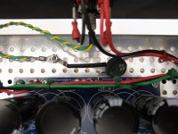
There are 2 ground holes betweeen the caps at the opposite end of the input from rectifiers. Put one leg of the cl60 there. Other leg to chassis.
Here is an example from one of 6L6’s build guides
Here is an example from one of 6L6’s build guides
Attachments
Last edited:

I have been battling with the cross channel ground loop for quite long time. Especially its very hard sometimes to debug it without knowing what's exactly happening.
Ill give my inputs with my experience. First thing first is to identify that which frequency is a problem like is it mains 60Hz or 120Hz. There are three possibilities here. Use spectrodroid app you measure using mobile phone when the speaker is on.
Only 60Hz means you have magnetic coupling happening because of your transformer as its radiating the magnetic field in the chassis:
Cure: you need to shield transformer with a mild steel and have the continuity to the chassis.
120Hz then the problem is a bit more complicated and simple solutions. So why are you hearing when other channel is connected? is that your ground has varied potential difference at two points and you need to use a thick 2.5sqmm or more wire to short these two grounds.
Now before knowing that what is actually creating that voltage difference is the flow of ground currents. In an amplifier this is more easier to fix than in preamp. First of all you need one star point where all your Main power supply capacitors gets to common point and that is the place where all your high current RETURN paths should get in contact like a sinking point. Now just like what Andrew suggested use T joint for the PSU capacitors and at the tail of that T joint you will have very little ground currents flowing through it or mostly zero and that's your ground reference to be connected. Believe me if you monitor how your ground currents are being flowing then you can easily debug the ground loop.