Hi Everyone,
It's been a few years since I did much electronics diy, or posted on the forum, but I've recently been doing more, including the kit from the diyaudio store of Nelson's new crossover; I'm also planning a new FW amp build, maybe M2X, maybe F3, to use with it.
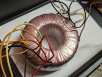
Searching out parts I came across a big toroidal transformer from a surplus site, which was cheap because it had few markings. I bought it on impulse, thinking I might need to rewind secondaries and that they might be fun (at least once). However after checking it out I'm wondering if I might be able to use it without doing anything. I've attached a couple of photos below.
It was sold to me as 1000VA, but I doubt it's as big as that. It weights about 11 or 12 pounds, is 5.5 inches in outside diameter, and about 2.5 inches high, so judging by this and other sites on the internet (like Rod Elliott's ESP site) it is more likely be between 500VA and 800VA. Which is still pretty big.
The side I presume is the primary (black/brown/white) has dual windings, each measures 2.6 ohms across black/brown, 2.2 ohms between black/white, and 0.6 ohms between brown/white. (This doesn't add up, but my meter may not be perfect, of course. Or maybe it's to be expected on a transformer.) The other (presumably secondary) side has four windings, all measuring the same, higher resistance. (Can't remember the value without checking.) Two are red/black, two are yellow/orange.
I tested it with a small AC voltage and then scaled up slowly. It turns out that if I connect the two primaries in series then each secondary gives slightly below 18V, which seems close enough. I used a modest load - can't remember precisely - so there was a reasonable current draw.
The plan is to wire the primaries in sequence, with a CL60 between them, as Nelson shows in his article on several FW amps. 110 V on this side, from the wall. Each of the secondaries would have its own rectifier bridge, and then all four would connect in parallel to a filter. With a little luck a big CLC filter, but that's not really relevant. (Although I note that in a thread of mine from a few years ago AndrewT said when secondaries are "bifillar", whatever that means, you can wire them in parallel to the same rectifier.)
So here are my questions.
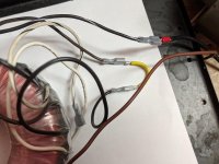
1. Is there any reason to think I have it the wrong way round, and this is some sort of transformer to scale low to high voltage? Doesn't seem likely - just thought I ought to check. The "primary" side has the clips shown in one of the photos, if that helps.
2. I doubt I'm proposing to wire the primary side the way it was intended. I don't think this makes any difference, does it? 110V on the primaries in series will produce half the voltage in the secondaries that 220V would, which was presumably the idea. So as long as I don't draw more current than is safe then there should be no problem, right?
3. What would the purpose be for the off-center tap on the primary side? I'm not planning on using it, but I'm curious.
4. Any reason my plan for using this in a stereo FW build wouldn't work? If so, is there any advantage to wiring the secondaries in some other way than what I propose?
Thanks in advance for any input.
Best
Nigel
It's been a few years since I did much electronics diy, or posted on the forum, but I've recently been doing more, including the kit from the diyaudio store of Nelson's new crossover; I'm also planning a new FW amp build, maybe M2X, maybe F3, to use with it.
Searching out parts I came across a big toroidal transformer from a surplus site, which was cheap because it had few markings. I bought it on impulse, thinking I might need to rewind secondaries and that they might be fun (at least once). However after checking it out I'm wondering if I might be able to use it without doing anything. I've attached a couple of photos below.
It was sold to me as 1000VA, but I doubt it's as big as that. It weights about 11 or 12 pounds, is 5.5 inches in outside diameter, and about 2.5 inches high, so judging by this and other sites on the internet (like Rod Elliott's ESP site) it is more likely be between 500VA and 800VA. Which is still pretty big.
The side I presume is the primary (black/brown/white) has dual windings, each measures 2.6 ohms across black/brown, 2.2 ohms between black/white, and 0.6 ohms between brown/white. (This doesn't add up, but my meter may not be perfect, of course. Or maybe it's to be expected on a transformer.) The other (presumably secondary) side has four windings, all measuring the same, higher resistance. (Can't remember the value without checking.) Two are red/black, two are yellow/orange.
I tested it with a small AC voltage and then scaled up slowly. It turns out that if I connect the two primaries in series then each secondary gives slightly below 18V, which seems close enough. I used a modest load - can't remember precisely - so there was a reasonable current draw.
The plan is to wire the primaries in sequence, with a CL60 between them, as Nelson shows in his article on several FW amps. 110 V on this side, from the wall. Each of the secondaries would have its own rectifier bridge, and then all four would connect in parallel to a filter. With a little luck a big CLC filter, but that's not really relevant. (Although I note that in a thread of mine from a few years ago AndrewT said when secondaries are "bifillar", whatever that means, you can wire them in parallel to the same rectifier.)
So here are my questions.
1. Is there any reason to think I have it the wrong way round, and this is some sort of transformer to scale low to high voltage? Doesn't seem likely - just thought I ought to check. The "primary" side has the clips shown in one of the photos, if that helps.
2. I doubt I'm proposing to wire the primary side the way it was intended. I don't think this makes any difference, does it? 110V on the primaries in series will produce half the voltage in the secondaries that 220V would, which was presumably the idea. So as long as I don't draw more current than is safe then there should be no problem, right?
3. What would the purpose be for the off-center tap on the primary side? I'm not planning on using it, but I'm curious.
4. Any reason my plan for using this in a stereo FW build wouldn't work? If so, is there any advantage to wiring the secondaries in some other way than what I propose?
Thanks in advance for any input.
Best
Nigel
Attachments
Hi Nelson,
Thanks for the speedy reply. I had no idea primaries were wound with 100V and 120V taps...
My concern in number 4 wasn't so much the voltage but current. If I set this up with a filter and adjustable load, and then slowly scale the current draw up then I should be fine as long as it doesn't get too hot. If I can get up to 4A or so (which is 1A per secondary) then I should be good to go, correct? Anything particular to watch out for?
And do you think separate rectifier bridges on all four secondaries is the best approach?
Incidentally, the site still lists what appears to be the same transformer, so maybe they had more than one - although I guess there's no guarantee it's exactly the same. If anyone else is interested it's here:
15-0040 Toroidal Transformer
At $39 it seems a pretty good deal, if it works. I'll keep you all posted.
Hi ZM,
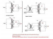
Yes, I think I understand this, although I'm proposing to connect the primaries in series, and apply just 110/115 to them. There are striped black, brown and white, and non-striped black, brown and white. If I connect the striped black to the non-striped black, as shown, and apply input voltage to the two ends, then this seems to work.
The left-hand side certainly does, although I'm having a harder time seeing how the right-hand side applies to my situation. It also raises another question; how do you tell what the "same end of the winding" is? If I connect the primaries as I just described, have I done it the way you showed in your left-hand diagram?
The secondaries are a little harder. In your diagram you show them as connected in series, but I'm planning on connecting them in parallel; potentially after the bridges, too. I've attached a diagram that shows the idea.
I am presuming that the two red/black pairs go the same way; that is, either black or red on both should have the red dot from your diagram. But if I have two others that are yellow/orange, then is it yellow or orange that should have the dot to match the red/black pairs? And if I've wired as in the diagram, does it matter?
Thanks!
it is most likely dual primary xformer, which means primaries in series for 220/230Vac, while in parallel for 110/115Vac
Yes, I think I understand this, although I'm proposing to connect the primaries in series, and apply just 110/115 to them. There are striped black, brown and white, and non-striped black, brown and white. If I connect the striped black to the non-striped black, as shown, and apply input voltage to the two ends, then this seems to work.
maybe this sketch will help
The left-hand side certainly does, although I'm having a harder time seeing how the right-hand side applies to my situation. It also raises another question; how do you tell what the "same end of the winding" is? If I connect the primaries as I just described, have I done it the way you showed in your left-hand diagram?
The secondaries are a little harder. In your diagram you show them as connected in series, but I'm planning on connecting them in parallel; potentially after the bridges, too. I've attached a diagram that shows the idea.
I am presuming that the two red/black pairs go the same way; that is, either black or red on both should have the red dot from your diagram. But if I have two others that are yellow/orange, then is it yellow or orange that should have the dot to match the red/black pairs? And if I've wired as in the diagram, does it matter?
Thanks!
Attachments
just go for it
though - you have that flag, while Maine as location
now - you have 18Vac at secondaries, if you wire primaries in series - using which mains voltage - 230 ( UK?) or 115Vac (Maine, USA?)
if latter, when using half mains voltage for xformer, you're getting just half of declared VA, when xformer used on full mains voltage
reason - wire size made for current, so with same allowable current, with half voltage you're getting just half of VA
anyway , if you're in Maine, USA - with some luck, you can feed regular FW jobbie, pulling up to 200VA for two channels, without xformer buzzing and heating
try, why not
edit - we typed in same time ...... but I think we covered it all
Hi ZM,
Yes, I think I understand this, although I'm proposing to connect the primaries in series, and apply just 110/115 to them. There are striped black, brown and white, and non-striped black, brown and white. If I connect the striped black to the non-striped black, as shown, and apply input voltage to the two ends, then this seems to work.
The left-hand side certainly does, although I'm having a harder time seeing how the right-hand side applies to my situation. It also raises another question; how do you tell what the "same end of the winding" is? If I connect the primaries as I just described, have I done it the way you showed in your left-hand diagram?
The secondaries are a little harder. In your diagram you show them as connected in series, but I'm planning on connecting them in parallel; potentially after the bridges, too. I've attached a diagram that shows the idea.
I am presuming that the two red/black pairs go the same way; that is, either black or red on both should have the red dot from your diagram. But if I have two others that are yellow/orange, then is it yellow or orange that should have the dot to match the red/black pairs? And if I've wired as in the diagram, does it matter?
Thanks!
look at sketch little more - you want to connect xformer ( for good or just to examine proper phasing) so VMeter can measure something, not to show 0Vac
in short - 0Vac on VM means - not good phasing
sketch is made to cover most of often asked questions, so ignore what's not interesting for your understanding
if you're going to deal with paralleling or whatever (with secondaries) after bridges - that's exact way which I can advise , and then secondary phasing is irrelevant, you deal with polarities afer bridges
I would go for dual mono with 4 independent 18Vac secs - using one bridge per secondary, and two of them for one channel, other two for second channel
just go for it
though - you have that flag, while Maine as location
now - you have 18Vac at secondaries, if you wire primaries in series - using which mains voltage - 230 ( UK?) or 115Vac (Maine, USA?)
Being British by birth I always liked having the UK flag, but I can see how it's misleading. Sorry for the confusion. I've changed it to the US flag. (Some of my old posts from when I lived in Brazil seem pretty strange now, but I guess it matters less.)
if latter, when using half mains voltage for xformer, you're getting just half of declared VA, when xformer used on full mains voltage
reason - wire size made for current, so with same allowable current, with half voltage you're getting just half of VA
Yes, I understand. On the other hand it looks large enough to handle what's needed. Also, is current in primary or in the secondary more likely to be the limiting factor? I guess it doesn't matter - it'll either hold up under the (dummy) load when I try it, or it won't...
anyway , if you're in Maine, USA - with some luck, you can feed regular FW jobbie, pulling up to 200VA for two channels, without xformer buzzing and heating
try, why not
Why not, indeed.
sketch is made to cover most of often asked questions, so ignore what's not interesting for your understanding
if you're going to deal with paralleling or whatever (with secondaries) after bridges - that's exact way which I can advise , and then secondary phasing is irrelevant, you deal with polarities afer bridges
Understood, thanks.
I would go for dual mono with 4 independent 18Vac secs - using one bridge per secondary, and two of them for one channel, other two for second channel
I already wondered about this, and it seems a very natural approach and has a lot of advantages. The only catch is that I have chokes to try a CLC filter, so with a dual mono I'll need to get two more the same. (Or four more of some other sort, I suppose.)
Thanks again for the help.
I just noticed an error in the diagram I posted above. Should be two pairs in parallel after the bridges, not all four paralleled. Although if I use ZM's suggestion of dual mono there will no paralleling involved, of course.
it's ok , we resumed that you are going to make bipolar supplies, so ...... all good
and yes - copper area is limiting factor - you'll hit ceiling with half voltages comparing to Good Olde, and VA of Donut is going to be half
and yes - copper area is limiting factor - you'll hit ceiling with half voltages comparing to Good Olde, and VA of Donut is going to be half
Hi ZM,
Thanks. I'm fishing around in my junk parts box looking for resistors to make dummy loads, but it looks like I don't have enough appropriate values on hand.
Like I said above, there is no VA rating written on the transformer and I'm skeptical of the store's claimed 1000VA. Guessing by size and weight the bottom end of my estimate range is around 600VA, so this would be 300VA the way I'm using it, which is a little small for a dual mono M2X, for instance. Whereas if it's originally around 800VA this is effectively 400VA to me, so I should be fine.
Would you hazard a guess as to it's VA rating by the size and weight I gave above?
Here's another thought.
The other amp I was thinking of building is an F3. This doesn't use a split supply, so I could use the primaries in parallel at 115/120 volts and get four secondaries all giving 35 or 36 VAC. I could then parallel them in two pairs (four rectifier bridges and/or taking ZM's observations on phase into account) and build a dual mono supply. This should preserve the original power rating (right?) and should be much more than is necessary for an F3.
This may be the better way to go, perhaps. Use this one for an F3, either now or later, and buy something that's a better fit for an M2X. (For which there are no boards in the store at present, anyhow.)
Anyone have thoughts or suggestions?
that would be best scenario
btw. take in account also that M2 ( counting that M2X is same biased as original) is pretty weeny biased- from top of my head , around 60W of heat per channel
still best to use that Donut in full voltage scenario
btw. take in account also that M2 ( counting that M2X is same biased as original) is pretty weeny biased- from top of my head , around 60W of heat per channel
still best to use that Donut in full voltage scenario
- Home
- Amplifiers
- Pass Labs
- Questions about big transformer with few markings