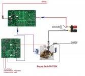
The Singing Bush Tips 'n' Tricks, so even Cheerleader Girlie can build it ...
....OK , here it is
ORIGIN THREAD : The Singing Bush
First few posts with graphical info, then I'll write separate posts for both amps, explaining few details
////////
however , most important thing when starting, applicable for both amps:
be sure that trimpot in buffer negative rail (lower JFet group source) is set to max position, prior to first powering up - check that measuring across parallel 39R resistor - reading must be close to 28R
/////////
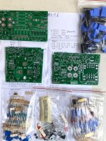
another thing - remove that silly blue collar from needle wire terminal you got from me - either use heat gun or heat it with solder or lighter ...... then pull it
all wires need to be crimped then soldered in wire terminals, then heatshrinked, to look nice
///////// ( you can see from these slashes that I spent some time recently struggling with Arduino )
)
for 2SK77B - lucky bstrdz having these - all 3W resistors in Mu part of amp - they are still 1R/3W , no change ........... Iq 3A2, output node or SIT Drain (what's easier to reach for measurement) set at approx U/2
///////////
edit 27.07.2020. - SIT Singing Bush startup procedure , post #29
....OK , here it is
ORIGIN THREAD : The Singing Bush
First few posts with graphical info, then I'll write separate posts for both amps, explaining few details
////////
however , most important thing when starting, applicable for both amps:
be sure that trimpot in buffer negative rail (lower JFet group source) is set to max position, prior to first powering up - check that measuring across parallel 39R resistor - reading must be close to 28R
/////////
another thing - remove that silly blue collar from needle wire terminal you got from me - either use heat gun or heat it with solder or lighter ...... then pull it
all wires need to be crimped then soldered in wire terminals, then heatshrinked, to look nice
///////// ( you can see from these slashes that I spent some time recently struggling with Arduino
)for 2SK77B - lucky bstrdz having these - all 3W resistors in Mu part of amp - they are still 1R/3W , no change ........... Iq 3A2, output node or SIT Drain (what's easier to reach for measurement) set at approx U/2
///////////
edit 27.07.2020. - SIT Singing Bush startup procedure , post #29
Last edited:
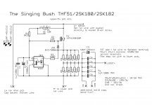
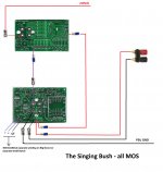
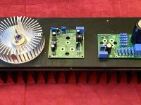
The Singing Bush SIT iteration
yup, this one is with THF51/2SK182/2SK180 in lower position
I know that few lucky bstrdz are having 2SK77B , to use there ....
I didn't drew input RCA and twisted pair of thin wires for that , you'll manage
yup, this one is with THF51/2SK182/2SK180 in lower position
I know that few lucky bstrdz are having 2SK77B , to use there ....
I didn't drew input RCA and twisted pair of thin wires for that , you'll manage
Attachments
do not reply - yet!
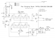
I'll finish later (evening, my time) with all MOS iteration, then you can ask/yell/complain/tease/praise/curse

I'll finish later (evening, my time) with all MOS iteration, then you can ask/yell/complain/tease/praise/curse
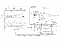
you need different set of 3W resistors , for THF
what you did solder is - all 1R/3W, adequate for Schade or 2SK77B SIT
what you did solder is - all 1R/3W, adequate for Schade or 2SK77B SIT
Oops. Ok, let's get this corrected. What do I need to run the big THF part?
I haven't found any info on the schematics, though the parts list had two lines crossed out, I could not understand what the preferred installation was.
I haven't found any info on the schematics, though the parts list had two lines crossed out, I could not understand what the preferred installation was.
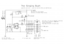
I think I figured out what I need for the THF-51. According to post #97 in the Singing Bush thread, we are trying to create the equivalent of a string of six 0R1 resistors, with the tap point 0R2 from the bottom, and 0R4 from the top.
So my bottom resistors are correct, but the top resistors need to be 3x 1R5 and 1x 2R2 for a total of 0.407 Ohms. Yes?
So my bottom resistors are correct, but the top resistors need to be 3x 1R5 and 1x 2R2 for a total of 0.407 Ohms. Yes?
Hi ZM,
In my version of amps (pre - Singing Bush) I recently tried speaker out at the middle of the resistors - THF - 0R3 - speaker - 0R3. With the THF-51S that I have, this gave better distortion results than speaker out at THF - 0R2 - speaker - 0R4.
Do you want to see the results?
In my version of amps (pre - Singing Bush) I recently tried speaker out at the middle of the resistors - THF - 0R3 - speaker - 0R3. With the THF-51S that I have, this gave better distortion results than speaker out at THF - 0R2 - speaker - 0R4.
Do you want to see the results?
So there it is.
My OCD required that I install a 2.0 Ohm resistor instead of the 2.2 included with the kit. I’m funny that way. Those big resistors are difficult to unsolder.
My OCD required that I install a 2.0 Ohm resistor instead of the 2.2 included with the kit. I’m funny that way. Those big resistors are difficult to unsolder.
Hi ZM,
In my version of amps (pre - Singing Bush) I recently tried speaker out at the middle of the resistors - THF - 0R3 - speaker - 0R3. With the THF-51S that I have, this gave better distortion results than speaker out at THF - 0R2 - speaker - 0R4.
Do you want to see the results?
certainly that I want
though , we see that there is no perfect recipe ...... in fact - every recipe is to get in ballpark, and fine tuning is always possible
without NFB and with so broad spread of transfer characteristics of used parts, we are pretty much lucky bstrdz anyway
There certainly is variability among the THF-51S. My two pieces are not identical.
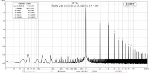
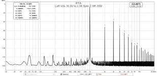
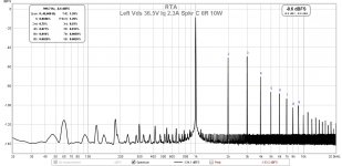
My amps are Vds=36.5V Iq=2.3A, same as your spec.
The following are left and right channels, speaker out between 0R2 and 0R4:
My amps are Vds=36.5V Iq=2.3A, same as your spec.
The following are left and right channels, speaker out between 0R2 and 0R4:
Attachments
-
 Right Vds 36,5V Iq 2,3A Spkr C 8R 30W.jpg146.5 KB · Views: 286
 -
 Right Vds 36,5V Iq 2,3A Spkr C 8R 20W.jpg145 KB · Views: 268
 -
 Right Vds 36,5V Iq 2,3A Spkr C 8R 10W.jpg145.5 KB · Views: 280
 -
 Right Vds 36,5V Iq 2,3A Spkr C 8R 5W.jpg146 KB · Views: 787
 -
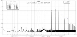 Left Vds 36,5V Iq 2,3A Spkr C 8R 30W.jpg147.4 KB · Views: 781
 -
 Left Vds 36,5V Iq 2,3A Spkr C 8R 20W.jpg147.4 KB · Views: 785
 -
 Left Vds 36,5V Iq 2,3A Spkr C 8R 10W.jpg145.5 KB · Views: 794
 -
 Left Vds 36,5V Iq 2,3A Spkr C 8R 5W.jpg147.2 KB · Views: 860
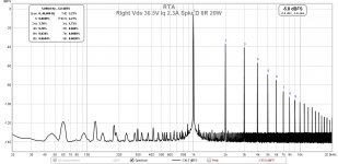
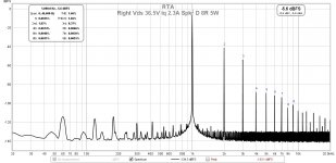
Here are left and right channels, speaker out between 0R3 and 0R3, Vgs=36.5V, Iq=2.3A:
Attachments
-
 Right Vds 36,5V Iq 2,3A Spkr D 20W.jpg146.4 KB · Views: 233
 -
 Right Vds 36,5V Iq 2,3A Spkr D 10W.jpg145.4 KB · Views: 240
 -
 Right Vds 36,5V Iq 2,3A Spkr D 5W.jpg145.8 KB · Views: 242
 -
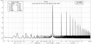 Left Vds 36,5V Iq 2,3A Spkr D 30W.jpg146.2 KB · Views: 231
 -
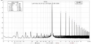 Left Vds 36,5V Iq 2,3A Spkr D 20W.jpg146.8 KB · Views: 237
 -
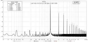 Left Vds 36,5V Iq 2,3A Spkr D 10W.jpg145.6 KB · Views: 283
 -
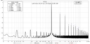 Left Vds 36,5V Iq 2,3A Spkr D 5W.jpg147.5 KB · Views: 278
 -
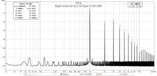 Right Vds 36,5V Iq 2,3A Spkr D 30W.jpg145.6 KB · Views: 236
as I see it from your graphs - with "my" values THD is lower at lower power levels, while with "your" values THD is lower at higher power levels
well, just let your ears decide ...... 🙂
well, just let your ears decide ...... 🙂
Yes, choices. I decided to go with the lower distortion at higher power levels, with higher second harmonic and lower third harmonic. 🙂
Hi Ben,
What is that wonderful device/piece of software that you are generating the graphs with? I'm sure the question "has been" asked before and I know its some form of distortion analyzer but beyond that I'm lost.
Jeffrey
What is that wonderful device/piece of software that you are generating the graphs with? I'm sure the question "has been" asked before and I know its some form of distortion analyzer but beyond that I'm lost.
Jeffrey
I used Room Equalization Wizard (REW) in conjunction with a Focusrite Scarlett USB sound card.
Howto - Distortion Measurements with REW
Howto - Distortion Measurements with REW
- Home
- Amplifiers
- Pass Labs
- The Singing Bush Tips 'n' Tricks