I finished my F5 build yesterday and wanted to document it before I lost motivation and moved on to another project. This was a great project, and I was happy to be making the most of my time in isolation creating something. My background is in software, and I don't expect to ever be able to fully understand or design analog electronics. But I really enjoy the process of building, customizing, refining, and chasing details.
Parts:
All PCBs are DiyAudio including the Universal Power Supply, F5, and Soft Start & Speaker Turn-On Delay / DC Protector Combo. I also purchased the F5 parts Kit, the LSK170/LSJ74 +/-0.1ma Matched Quad and Back panel parts kit plus PCB / Transistor / Diode mounting parts kit for the Deluxe Chassis.
The large transformer is a CM0500218 230V (2x115V) 500VA 2x18V audio grade toroid from Airlink. It's ok, but the finish was a tad sloppy, and the shipping was high. I would probably gibe Toroidy a try for a future project. The small transformer powers the speaker protection boards and is an RS 230V (2x115V) 15VA 2x12V.
All components (aside form the DiyAudio kit parts and transformers) came from Mouser. Shipping from Texas to Spain was free and was only 3 business days from placing the order to arrival.
For wire I used what I had nearby. Power (e.g. IEC -> terminal -> soft start) is 1.5mm2 taken from an IKEA extension cord. The same was used for the PSU to amp boards, chassis grounding, audio ground lift, etc. For amp boards to speaker protection and speaker terminals I borrowed an unneeded foot or two from my speaker cables, which are DCSk 2.5mm2. Signal inputs to amp boards is twisted pair stripped from CAT5 cables.
I also made a dim-bulb tester from an IEC cable, a ceiling lamp socket kit, and a 100w incandescent bulb. It never actually saved me from any mistakes, but it did make switching it on the first time and after each change less stressful.
Build:
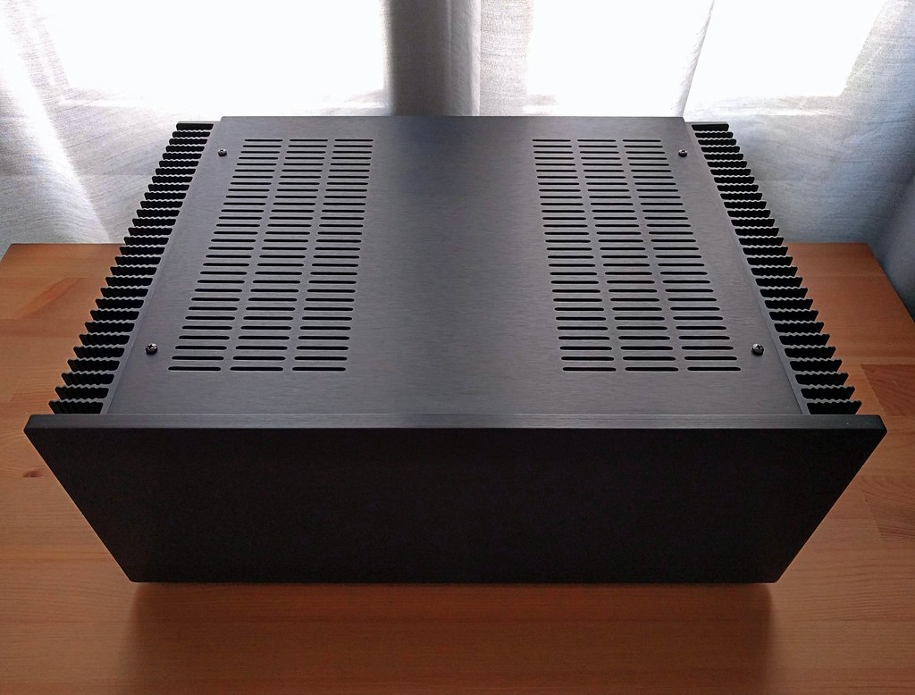
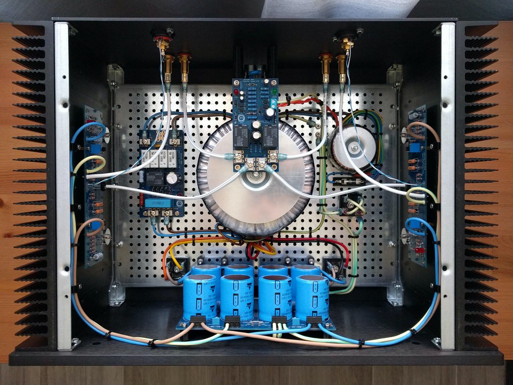
I was expecting more room in this big 4U chassis, but it's actually compact inside once I added the 500VA PSU, soft start, and speaker protection boards, second transformer, etc. I ordered the black 10mm aluminum faceplate which doesn't have convenient tapped holes like the silver version. So I had to get creative some of the layout and decided to design and 3D print some parts to make it cleaner and easier to work on.
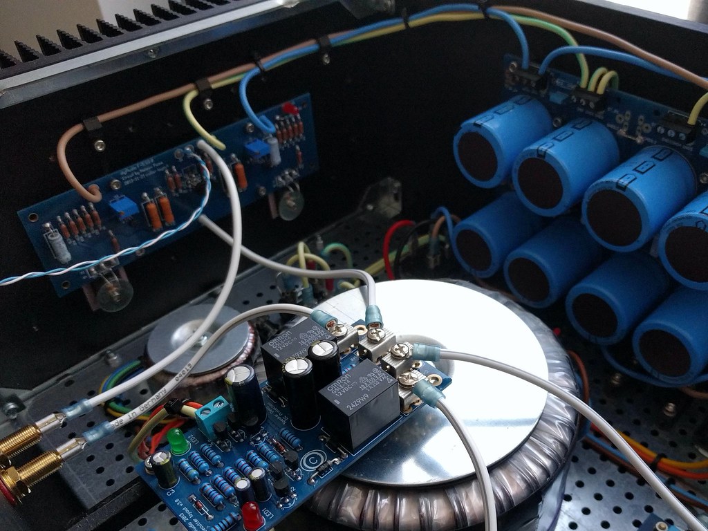
I designed and printed L-shaped brackets to hold the PSU PCB against the faceplate. The bracket only anchors to the bottom plate which makes it convenient when removing the faceplate for better access. The soft start board is on the bottom plate next to the transformer. The speaker protection board is on 3D printed inverted L-shaped brackets I designed that attach to the back panel by sharing the IEC inlet/fuse mounting hardware. The board is only supported from one end at the moment, but I plan to create a second bracket that will anchor to the transformer mounting plate. I also designed and printed some cable guides that attach to the heat sinks via some of the spare tapped holes.
I spent quite a lot of time on layout of boards, transformers, wires, etc. because I enjoy it, and I've had a lot of time recently. I left all the primaries and secondaries at full length just in case I want to make changes, try a different amp build, convert to 115V, etc.
Sound:
No idea! To be honest I did this project more for the journey than the end result. I will definitely put it to use soon, but I don't have a preamp at the moment -- just a couple integrated amps (Rega Brio-R and Sony TA-F3000ES). I have a ChromeCast Audio and a couple Raspberry Pi DACs with variable outputs, but there's something to be said for having a potentiometer in between a source and amp in case there's a 'glitch'.
So I don't have more to say on this at the moment, but will add to this thread when I build or buy a preamp for it. My current plan is to build the Mezmerize B1 Buffer, which would give me another couple of weeks of entertainment value.
Photos:
Below are a few shots I took today, and more high-res ones can be found in this album.


Parts:
All PCBs are DiyAudio including the Universal Power Supply, F5, and Soft Start & Speaker Turn-On Delay / DC Protector Combo. I also purchased the F5 parts Kit, the LSK170/LSJ74 +/-0.1ma Matched Quad and Back panel parts kit plus PCB / Transistor / Diode mounting parts kit for the Deluxe Chassis.
The large transformer is a CM0500218 230V (2x115V) 500VA 2x18V audio grade toroid from Airlink. It's ok, but the finish was a tad sloppy, and the shipping was high. I would probably gibe Toroidy a try for a future project. The small transformer powers the speaker protection boards and is an RS 230V (2x115V) 15VA 2x12V.
All components (aside form the DiyAudio kit parts and transformers) came from Mouser. Shipping from Texas to Spain was free and was only 3 business days from placing the order to arrival.
For wire I used what I had nearby. Power (e.g. IEC -> terminal -> soft start) is 1.5mm2 taken from an IKEA extension cord. The same was used for the PSU to amp boards, chassis grounding, audio ground lift, etc. For amp boards to speaker protection and speaker terminals I borrowed an unneeded foot or two from my speaker cables, which are DCSk 2.5mm2. Signal inputs to amp boards is twisted pair stripped from CAT5 cables.
I also made a dim-bulb tester from an IEC cable, a ceiling lamp socket kit, and a 100w incandescent bulb. It never actually saved me from any mistakes, but it did make switching it on the first time and after each change less stressful.
Build:
I was expecting more room in this big 4U chassis, but it's actually compact inside once I added the 500VA PSU, soft start, and speaker protection boards, second transformer, etc. I ordered the black 10mm aluminum faceplate which doesn't have convenient tapped holes like the silver version. So I had to get creative some of the layout and decided to design and 3D print some parts to make it cleaner and easier to work on.
I designed and printed L-shaped brackets to hold the PSU PCB against the faceplate. The bracket only anchors to the bottom plate which makes it convenient when removing the faceplate for better access. The soft start board is on the bottom plate next to the transformer. The speaker protection board is on 3D printed inverted L-shaped brackets I designed that attach to the back panel by sharing the IEC inlet/fuse mounting hardware. The board is only supported from one end at the moment, but I plan to create a second bracket that will anchor to the transformer mounting plate. I also designed and printed some cable guides that attach to the heat sinks via some of the spare tapped holes.
I spent quite a lot of time on layout of boards, transformers, wires, etc. because I enjoy it, and I've had a lot of time recently. I left all the primaries and secondaries at full length just in case I want to make changes, try a different amp build, convert to 115V, etc.
Sound:
No idea! To be honest I did this project more for the journey than the end result. I will definitely put it to use soon, but I don't have a preamp at the moment -- just a couple integrated amps (Rega Brio-R and Sony TA-F3000ES). I have a ChromeCast Audio and a couple Raspberry Pi DACs with variable outputs, but there's something to be said for having a potentiometer in between a source and amp in case there's a 'glitch'.
So I don't have more to say on this at the moment, but will add to this thread when I build or buy a preamp for it. My current plan is to build the Mezmerize B1 Buffer, which would give me another couple of weeks of entertainment value.
Photos:
Below are a few shots I took today, and more high-res ones can be found in this album.
Last edited:

On the critical side, do I see signal wires going right over the transformer?
Yes, and I may try rerouting or putting an enclosure over the transformer if it's a problem. A lot of posts suggested having the shortest run possible for signal wires so I went for that first. I've got twisted pair left over if I need to try routing around the edges of the chassis.
Yes, and I may try rerouting or putting an enclosure over the transformer if it's a problem. A lot of posts suggested having the shortest run possible for signal wires so I went for that first. I've got twisted pair left over if I need to try routing around the edges of the chassis.
For the second time: Very, very, very nice job!

I saw that in the DIYAudio Store everything is available for F5, you made me want to try to make one ... ok, maybe then I will have to sleep in the garage or in the garden for the next two years (my wife
 ...), but I think I want to do it!
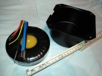
Your creation has a really clean layout, for this I would not change the position of the cables, you can shield the transformer with an enclosure like the one in the pic, I purchased it on Aliexpress, there are in many sizes.
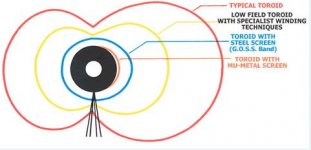
In any case, the enclosure material must be ferrous like mild steel, not stainless steel, aluminum, copper or lead, as these are not non-magnetic and only stop the electric field, not the magnetic field.
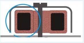
If you make this choice, remember very well what Zen Mod wrote in "Pictures of your Pass amplifier" # 5168, this is very important.
Ok, enjoy your music!
Mauro
Attachments
For the second time: Very, very, very nice job!
I saw that in the DIYAudio Store everything is available for F5, you made me want to try to make one ... ok, maybe then I will have to sleep in the garage or in the garden for the next two years (my wife
Your creation has a really clean layout, for this I would not change the position of the cables, you can shield the transformer with an enclosure like the one in the pic, I purchased it on Aliexpress, there are in many sizes.
In any case, the enclosure material must be ferrous like mild steel, not stainless steel, aluminum, copper or lead, as these are not non-magnetic and only stop the electric field, not the magnetic field.
If you make this choice, remember very well what Zen Mod wrote in "Pictures of your Pass amplifier" # 5168, this is very important.
Ok, enjoy your music!
Mauro
Thanks for the compliments. I do really like the way it is laid out and hope it works just like this, but if it doesn't I will probably buy one of those cans from ebay or somewhere else. Good point about the ferrous requirement -- I've seen some nice aluminum ones but they would be more decorative and less useful.
My transformer came with some kind of metal band/belt about 4 cm wide that I took off because it was poorly made and had sharp edges. But I should at least see if it is ferrous because it could give some benefit if I find problems with hum.
@ booja30 - the metal belt around your transformer was certainly a screen, try to bring a magnet close to it and you will immediately see if it is ferrous or not.
Of course, if it doesn't create problems in my point of view it's nice to see the naked toroidal, I think it gives a feeling of "power". Otherwise, I have seen really beautiful cans in anodized aluminum or polished stainless steel in online stores.
If this is not enough for shielding, there is a material that has solved many problems in the instrumentation that I normally use at work, the Mu-metal.
Search on Google, this is available in sheets or belt, you can also coat the can internally, always respecting the rules of the closed loop.
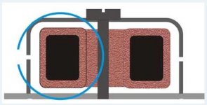
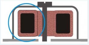
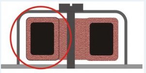
I attach some pictures on what to do and what not to do with the toroidal shields.
Of course, if it doesn't create problems in my point of view it's nice to see the naked toroidal, I think it gives a feeling of "power". Otherwise, I have seen really beautiful cans in anodized aluminum or polished stainless steel in online stores.
If this is not enough for shielding, there is a material that has solved many problems in the instrumentation that I normally use at work, the Mu-metal.
Search on Google, this is available in sheets or belt, you can also coat the can internally, always respecting the rules of the closed loop.
I attach some pictures on what to do and what not to do with the toroidal shields.
Attachments
.......
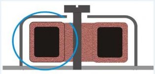
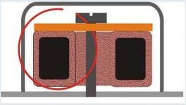
I attach some pictures on what to do and what not to do with the toroidal shields.
damn good example of informative and clear explanation post!
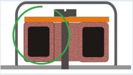
though, last one should be green 🙂
......
though, last one should be green 🙂
Absolutely yes, thanks for the correction
Absolutely yes, thanks for the correction
Now it's ok 🙂 Thanks Zen Mod!
Attachments
boojah30, I can only handle so much cable and build porn so early in the day. That is amazing and would definitely be the visial (and sonic) centerpiece of any system.
However, I am highly suspicious because no build can be that textbook perfect. You show us pictures of your F5, but I am guessing that there is just a tonne of tool Mark's, scratches, New York style graffiti, and deep gouges scarring the back and the bottom of the case.
Please send the F5 to me so I can investigate further. 😉
Thanks for the compliment. I had one scary moment where it looked like I had made a lentil sized chip through the black anodizing in the middle of the faceplate. It turns out it was actually a stray blob of solder that had been squished between the table and the faceplate when I had turned it on end. It came off with some gentle prodding.
Ok, there were other scary moments, like when I used the dim bulb tester after making some grounding changes, and I had already biased it to 0.4V. I forgot that you're supposed to only use the dim bulb tester before it is biased up.
Fun stuff!
Ok, there were other scary moments, like when I used the dim bulb tester after making some grounding changes, and I had already biased it to 0.4V. I forgot that you're supposed to only use the dim bulb tester before it is biased up.
Fun stuff!
boojah30, I can only handle so much cable and build porn so early in the day. That is amazing and would definitely be the visial (and sonic) centerpiece of any system.
However, I am highly suspicious because no build can be that textbook perfect. You show us pictures of your F5, but I am guessing that there is just a tonne of tool Mark's, scratches, New York style graffiti, and deep gouges scarring the back and the bottom of the case.
Please send the F5 to me so I can investigate further. 😉
- Home
- Amplifiers
- Pass Labs
- F5 build wrap-up