Obviously I have almost no knowledge, but with some fidgeting and an external board, could this be made into a selectable switch to different target impedances? It could be a fun project, although, as said, I know very little about this.Yes, both channels. I was too lazy to show the other channel.
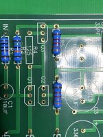
Change R16 and R17 and add "R" to both channels.
I added "R" to the bottom of the board.
Even maybe a two position switch: 32Ohm, XOhm (in my case 300).
I had a couple of small value film caps lying around so I used them on the input cap, C1.
Thanks for the info. I'll stop asking questions now 🙂 . Thanks again.
Obviously I have almost no knowledge, but with some fidgeting and an external board, could this be made into a selectable switch to different target impedances? It could be a fun project, although, as said, I know very little about this.
Even maybe a two position switch: 32Ohm, XOhm (in my case 300).
Hmmm now that's a great idea...one that I wish I'd thought of before my second Mouser order for this project🙄 So it goes...Something to add to my next order. 🙂
Another VFET lottery contender 🙂
Huh? I think you may have posted in the wrong place🙁
You'll have another chance in about 11 hours 11minutes from now.
So I de-soldered several of the caps and transistors and mostly the caps seem to be within 20% spec and the transistors are at least recognized by my parts tester. A couple bits broke in the process so at this point I'll at very least be ordering some new parts.
So from here, some questions:
a) At this point I think I'll replace all caps and transistors to be safe...is there anything else that could have been affected? Resistors? PCB?
b) The caps I had all seem to be within 10-20% tolerance...is that good enough for this project? It seems that's the norm for electrolytic caps but I'm new to amp building and from the pics of different builds there seems to be a wide variety to form factors within "spec."
c)What would I want to specifically test with the transistors I may have shorted?
First, buy one of these to check the status of the transistors:
https://www.amazon.com/Mega328-Digi...&qid=1618034836&sprefix=meg328,aps,223&sr=8-6
The tester will display the type of the transistors, the pin out, Vp, and Idss. The last 2 readings are not accurate, but if you get all these readings, then the device being tested is very much alive.
In (a), you already plan the worst case to replace all the transistor and the caps, you really have nothing to lose. If all the transistors are checked out OK, then the damage is very likely to be isolated to R18, C6. In a previous post, you said you had replace R18, R19, C6, C7, so very much, you just solder everything back and give it a test. The only change that you need to make is to change R4 to 50R.

This post and the surrounding discussion may be of interest.
https://www.diyaudio.com/forums/pass-labs/321925-diyaudio-watt-m2x-450.html#post6536256
https://www.diyaudio.com/forums/pass-labs/321925-diyaudio-watt-m2x-450.html#post6536256
Thank you!
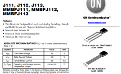
Yes, I can confirm the ON datasheet is wrong. I have freshly bought ON parts and they follow the Fairchild pinout, so the silk is correct on the board.
BTW, so far out of the bag mine use 10R source resistor to get approx. 10mA. So wide variation here.
🙂
Yes, I can confirm the ON datasheet is wrong. I have freshly bought ON parts and they follow the Fairchild pinout, so the silk is correct on the board.
BTW, so far out of the bag mine use 10R source resistor to get approx. 10mA. So wide variation here.
🙂
I burnt a few out discovering this. I decided that there must be two pinout versions in the wild:
The Fairchild (now part of ON) shows the same pinout as the ACP+ board
The ON data sheet (and also the InterFet datasheet) show the same pinout as each other but I have not bought either of these so can not confirm this.


The Fairchild (now part of ON) shows the same pinout as the ACP+ board
The ON data sheet (and also the InterFet datasheet) show the same pinout as each other but I have not bought either of these so can not confirm this.
Last edited:
See this post
https://www.diyaudio.com/forums/solid-state/343164-udness-dont-semisouths-31.html#post6618584
It looks like ON spec sheet can be correct, but at some point, Mouser was hosting a bad one....
BTW, that is another interesting project that doesn't require hard to get parts.
https://www.diyaudio.com/forums/solid-state/343164-udness-dont-semisouths-31.html#post6618584
It looks like ON spec sheet can be correct, but at some point, Mouser was hosting a bad one....
BTW, that is another interesting project that doesn't require hard to get parts.
I built two ACP+.
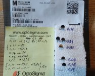
I ordered 10 pcs. ON J113 from Mouser.
Access to this page has been denied.
I was able to pick 3 well matched pairs.I used the ACP+ pcb pinout.
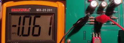
You can see the IDSS values on the left side, right are the R4 values on the yellow sticky note.
I measured the R4 values with a lab supply (11,x V) and a trimmer pot.
I built one ACPs with 100 R R4, and I used 124 R for the other one.
This is a very good little amp.
Thanks Papa and diyAudio folks!
I ordered 10 pcs. ON J113 from Mouser.
Access to this page has been denied.
I was able to pick 3 well matched pairs.I used the ACP+ pcb pinout.
You can see the IDSS values on the left side, right are the R4 values on the yellow sticky note.
I measured the R4 values with a lab supply (11,x V) and a trimmer pot.
I built one ACPs with 100 R R4, and I used 124 R for the other one.
This is a very good little amp.
Thanks Papa and diyAudio folks!
Attachments
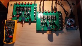
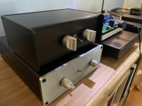
My ACP+ lurched to life last night!
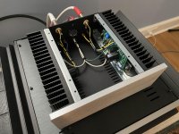
Nelson, if you're looking, I think this is a really spectacular project. Sounds terrific! And just in case you think I'm a lazy bum who never builds anything. Here's my B1 and Amp Camp, all finished in the last week. 🙂
Nelson, if you're looking, I think this is a really spectacular project. Sounds terrific! And just in case you think I'm a lazy bum who never builds anything. Here's my B1 and Amp Camp, all finished in the last week. 🙂
Attachments
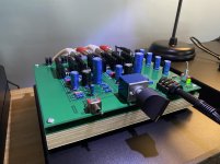
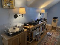
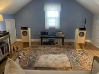

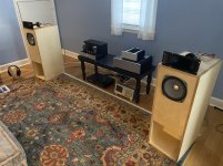
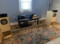
OMG. This is awesome! Love seeing other systems (especially expert ones ;-). Besides everything else—the Baltic-ply plinth under the ACP+ is VERY nice. Scope in the official listening space? YES!
- Home
- Amplifiers
- Pass Labs
- Amp Camp Pre+Headphone Amp - ACP+