I've been into DIY audio for more than 35 years and its time to give something back to the community...
You're free to use the provided information for your own personal projects but not for any commercial business.
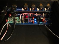
For the fun of it I made myself an everyday control unit...
Highlights
A YouTube video as a teaser can be seen here.
Let's dive deeper into each area mentioned above:
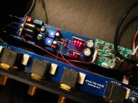
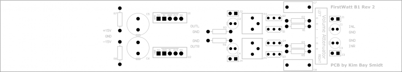
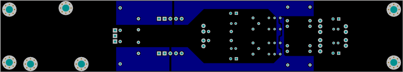
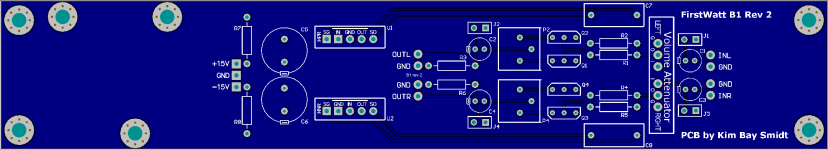
1. B1 rev 2
I designed by own printed circuit board with the following features:
I'll later provide the PCB files for production and recommend a PCB manufacture that works for me.
(I've a few boards available, send me PM, first come, first served.)
More info about the B1 rev 2 can be found here.
2. MUSES72320 electronic volume
The volume control is based on NJR MUSES 72320
Passlabs use this as volume control in their top preamp(s?).
As Passlabs I only use the first attenuator and I've no buffer in front so the impedance of the input is in the range of 14-20 KOhm according to the datasheet.
The schematic and PCB layout will follow in a later post...
I'll also provide the PCB files for production and recommend a PCB manufacture that works for me.
(I've a few boards available, send me PM, first come, first served.)
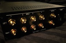
3. Relay based input
Samuel Groner and Bruno Putzeys published a short article with measurements in Linear Audio Vol 13. The article can be bought online here.
After I read the article I couldn't chose any other relay than what Bruno Putzeys use in the mola-mola products... 🙄
4. SilentSwitcher power supply
A brilliant low-noise DC-DC voltage regulator designed by Jan Didden. I use it for everything possible even for my Well Tempered Amadeus turntable!
There's a diyaudio thread about the SilentSwitcher here.
You can buy the SilentSwitcher in the diyaudio store here.
5. Hypex voltage regulators
The original SilentSwitcher outputs +/-15 Volt and I had to lower that a bit and I chose the low-drop out regulators from Hypex.
My PCB for the B1 is designed with Kelvin sense connections to provide point-of-load (local) regulation without requiring physical proximity of the Hypex regulators.
You're can also use ordinary 3-pin voltage regulators or chose the SilentSwitcher MKII that can be customized to output +/-12 Volt and skip the extra voltage regulators.
6. LED dot matrix display
I chose a LED dot matrix display as they're readable on distance even in very bright light. The drawback is switching noise from the multiplexer has to be handled.
To keep things as simple as possible I chose a display kit from Adafruit:
Adafruit 0.8" 8x16 LED Matrix FeatherWing Display Kit - Red
And to make the mounting of display easy I chose to solder some short female headers on the microcontroller board:
Short Feather Headers Kit - 12-pin and 16-pin Female Header Set
7. Arduino microcontroller
The microcontroller is an Adafruit Feather 328P - Atmega328P 3.3V @8 MHz.
USD 12.50... what not to like? 😀
8. Apple remote control
The control unit is remotely controlled by an Apple Remote
I just love the small Apple aluminium remote. I also use it for my main preamp (Vacuum State RTP3D) and my friend and fellow diyaudio member Fonnesbek made the c code for it at the time.
Most of the code for the Apple remote in my control unit discussed here is based on the code made by hifiduino. I just made it work on the Arduino. I might publish the Arduino code itself on Github.
I made the code for auto-pairing the Apple remote to the control unit so where would be no conflicts with other Apple remotes in the same room.
The first time the control unit receives an IR code after powering up that specific Apple remote is locked to the control unit.
The pairing is lost when the microcontroller loose its power. A clever move if you think a little about it.
9. Open source code
Beware that I'm not educated in programming so ugly hacks is to easily found in my code. That said I find the code bug free and highly usable.
I'll make my source code available on GitHub in the near future.
You're free to modify and fork it into your own edition when credited to me (and including 'hifiduino' for his code used for the Apple remote).
The source code shall remain open source and may not be used for any commercial products what so ever.
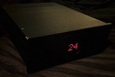
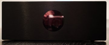
10. Case for the control unit
I use a well known all aluminium case from Hifi2000 in Italy.
--
More information to follow in the days to come.
If any of the provided information is faulty or can be optimised for an even better end user experience feel free to post your comments.
You're free to use the provided information for your own personal projects but not for any commercial business.
For the fun of it I made myself an everyday control unit...
Highlights
- B1 rev 2
- MUSES 72320 volume
- Relay based input
- SilentSwitcher power supply
- Hypex voltage regulators
- LED dot matrix display
- Arduino microcontroller
- Apple remote control
- Open source code
- Case for the control unit.
A YouTube video as a teaser can be seen here.
Let's dive deeper into each area mentioned above:
1. B1 rev 2
I designed by own printed circuit board with the following features:
- Optional input and output coupling capacitors (on board bypass jumpers)
- Optional MUSES 72320 volume
- DC-adjustment
- Prepared for use of (Hypex) voltage regulators
- Prepared for use of the brilliant SilentSwitcher.
I'll later provide the PCB files for production and recommend a PCB manufacture that works for me.
(I've a few boards available, send me PM, first come, first served.)
More info about the B1 rev 2 can be found here.
2. MUSES72320 electronic volume
The volume control is based on NJR MUSES 72320
Passlabs use this as volume control in their top preamp(s?).
As Passlabs I only use the first attenuator and I've no buffer in front so the impedance of the input is in the range of 14-20 KOhm according to the datasheet.
The schematic and PCB layout will follow in a later post...
I'll also provide the PCB files for production and recommend a PCB manufacture that works for me.
(I've a few boards available, send me PM, first come, first served.)
3. Relay based input
Samuel Groner and Bruno Putzeys published a short article with measurements in Linear Audio Vol 13. The article can be bought online here.
After I read the article I couldn't chose any other relay than what Bruno Putzeys use in the mola-mola products... 🙄
4. SilentSwitcher power supply
A brilliant low-noise DC-DC voltage regulator designed by Jan Didden. I use it for everything possible even for my Well Tempered Amadeus turntable!
There's a diyaudio thread about the SilentSwitcher here.
You can buy the SilentSwitcher in the diyaudio store here.
5. Hypex voltage regulators
The original SilentSwitcher outputs +/-15 Volt and I had to lower that a bit and I chose the low-drop out regulators from Hypex.
My PCB for the B1 is designed with Kelvin sense connections to provide point-of-load (local) regulation without requiring physical proximity of the Hypex regulators.
You're can also use ordinary 3-pin voltage regulators or chose the SilentSwitcher MKII that can be customized to output +/-12 Volt and skip the extra voltage regulators.
6. LED dot matrix display
I chose a LED dot matrix display as they're readable on distance even in very bright light. The drawback is switching noise from the multiplexer has to be handled.
To keep things as simple as possible I chose a display kit from Adafruit:
Adafruit 0.8" 8x16 LED Matrix FeatherWing Display Kit - Red
And to make the mounting of display easy I chose to solder some short female headers on the microcontroller board:
Short Feather Headers Kit - 12-pin and 16-pin Female Header Set
7. Arduino microcontroller
The microcontroller is an Adafruit Feather 328P - Atmega328P 3.3V @8 MHz.
USD 12.50... what not to like? 😀
8. Apple remote control
The control unit is remotely controlled by an Apple Remote
I just love the small Apple aluminium remote. I also use it for my main preamp (Vacuum State RTP3D) and my friend and fellow diyaudio member Fonnesbek made the c code for it at the time.
Most of the code for the Apple remote in my control unit discussed here is based on the code made by hifiduino. I just made it work on the Arduino. I might publish the Arduino code itself on Github.
I made the code for auto-pairing the Apple remote to the control unit so where would be no conflicts with other Apple remotes in the same room.
The first time the control unit receives an IR code after powering up that specific Apple remote is locked to the control unit.
The pairing is lost when the microcontroller loose its power. A clever move if you think a little about it.
9. Open source code
Beware that I'm not educated in programming so ugly hacks is to easily found in my code. That said I find the code bug free and highly usable.
I'll make my source code available on GitHub in the near future.
You're free to modify and fork it into your own edition when credited to me (and including 'hifiduino' for his code used for the Apple remote).
The source code shall remain open source and may not be used for any commercial products what so ever.
10. Case for the control unit
I use a well known all aluminium case from Hifi2000 in Italy.
- Hifi2000 Galaxy Maggiorato GX288 230 x 280 mm, all panels are aluminium
- Hifi2000 Galaxy Maggiorato 10mm front panel, black
- Custom CNC machined panels: front, back and bottom
- Discrete text on the front panel (black in-fill color)
- Easy readable text on the back panel (white in-fill color)
- 1 mm clear pipe for the red LED on the front panel.
- All metal work made by a professional company in Germany to my specifications.
- Red perspex is press fit into the front panel.
--
More information to follow in the days to come.
If any of the provided information is faulty or can be optimised for an even better end user experience feel free to post your comments.
Attachments
Last edited:
That's very nice Kim.
I like the modular design, it is possible to try LT3045 and 3094 LDO modules in your design. Almost same price, but better parameters.
LT3045-78XX Ultra Low Noise LDO Voltage Regulator
LT3094-79XX Ultra Low Noise LDO Voltage Regulator Negative Output
I am interested in pcbs, if possible 🙂
I like the modular design, it is possible to try LT3045 and 3094 LDO modules in your design. Almost same price, but better parameters.
LT3045-78XX Ultra Low Noise LDO Voltage Regulator
LT3094-79XX Ultra Low Noise LDO Voltage Regulator Negative Output
I am interested in pcbs, if possible 🙂
I really look forward to seeing your Arduino code, Kim.
I've succeeded in some arduino code running things, but I've spent a little
time looking into running the MAXIM chip. My tail is down 🙂
I'm certainly much worse in programming than you are if you got it working. I stand to learn a thing or ten no matter how ugly you say your code is 🙂
I've succeeded in some arduino code running things, but I've spent a little
time looking into running the MAXIM chip. My tail is down 🙂
I'm certainly much worse in programming than you are if you got it working. I stand to learn a thing or ten no matter how ugly you say your code is 🙂
Thank you.
As IDE (integrated development environment) for the programming I preferred Apple Xcode over Arduino.
I'll have to ensure I can compile the code with the Arduino IDE before making the code public. And then I might make the code public via Arduino instead of Github. We will see.
Before covering the code I'll cover the other topics first.
Stay tuned.
I really look forward to seeing your Arduino code, Kim.
I've succeeded in some arduino code running things, but I've spent a little
time looking into running the MAXIM chip. My tail is down 🙂
I'm certainly much worse in programming than you are if you got it working. I stand to learn a thing or ten no matter how ugly you say your code is 🙂
1. B1 rev 2 - schematic & PCB
A better photo of the front panel below. The red perspex looks more black than red in real life under normal light conditions.
The production files (Gerber files) will follow when I have the gut feeling that they are more right than wrong (my PCB manufacture handles my pcb files directly so I newer do Gerber files that I find to be PITA to get right.
Attachments
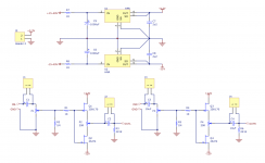
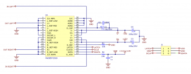
2. MUSES 72320 volume
This posting includes PCB-production files for the MUSES72320 volume in two formats:
- Gerber files (unzip: MUSES72320_PCB_Gerber.zip)
- Protel (unzip: MUSES72320_PCB_Protel.PcbDoc.zip)
I'm no Gerber expert so the Gerber files might include errors for the production. My pcb manufacturer (PCB Manufacturing and Assembly All in One Place | PCBCart) always send me a PDF file for my inspection before they start the production - excellent service.
For you convenience I've also included a BOM. In the spirit of Mr. Pass please use what you have. For surface mounted resistors I prefer thin film resistors over thick film for a bit lower distortion.
Feel free to comment errors and suggest optimisation to my design.
Attachments
-
MUSES72320_PCB_Protel.PcbDoc.zip232.6 KB · Views: 89
-
MUSES72320 BOM.pdf28 KB · Views: 186
-
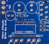 MUSES72320_PCB.jpg142 KB · Views: 267
 -
 MUSES72320_PCB_top_overlay.png99.8 KB · Views: 205
 -
 MUSES72320_PCB_bottom.png24.2 KB · Views: 222
 -
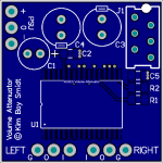 MUSES72320_PCB_top.png36.5 KB · Views: 333
 -
 MUSES72320_schematic.png203.4 KB · Views: 356
 -
MUSES72320_PCB_Gerber.zip23.8 KB · Views: 93
My 2 cents on the arduino code.
I did a wifi remote on the boards with dip switches which combine the Uno and ESP8622.
For those persistant it can be found on these links
my Wi-Fi remote control
Its everything for two on/off buttons, two press and hold for the pot. There is a bit missing for when wi fi connection drops.
I did a wifi remote on the boards with dip switches which combine the Uno and ESP8622.
For those persistant it can be found on these links
my Wi-Fi remote control
Its everything for two on/off buttons, two press and hold for the pot. There is a bit missing for when wi fi connection drops.
Kim - quick question. Are you using the same +/- rails for the Muses that are for the audio B1R2 section?
Many thanks
Many thanks
Slow answer...
No.
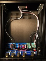
+/- rails for the Muses are taken directly from the output of the SilentSwitcher.
You can see a 3-wire ribbon cable in the photos.
No.
+/- rails for the Muses are taken directly from the output of the SilentSwitcher.
You can see a 3-wire ribbon cable in the photos.
Kim - quick question. Are you using the same +/- rails for the Muses that are for the audio B1R2 section?
Many thanks
thanks for the slow reply 🙂
I will re-formulate my question as I'm not sure it was as clear as it should have been.
Are the +/- rails for the Muses chip and the B1r2 circuit derived from the same +/- PSU (silent switcher), or are they fed by independent PSUs?
TIA
I will re-formulate my question as I'm not sure it was as clear as it should have been.
Are the +/- rails for the Muses chip and the B1r2 circuit derived from the same +/- PSU (silent switcher), or are they fed by independent PSUs?
TIA
Derived from the same SilentSwitcher.
The B1r2 circuit has its own regulators just to bring down the Voltage.
The B1r2 circuit has its own regulators just to bring down the Voltage.
thanks for the slow reply 🙂
I will re-formulate my question as I'm not sure it was as clear as it should have been.
Are the +/- rails for the Muses chip and the B1r2 circuit derived from the same +/- PSU (silent switcher), or are they fed by independent PSUs?
TIA
I was recommended checking out this thread which I just did, looks very interesting. Any updates, like the code etc ?
No updates at this time, sorry.I was recommended checking out this thread which I just did, looks very interesting. Any updates, like the code etc ?
Limited time due to family and work...
I have been waiting for ages for someone to do something like this, I was about to do it myself thinking no one had done it.
Awesome work.
Can you control the muses chip with some kind of rotary potentiometer/controller, I am not interested in remote control?
Awesome work.
Can you control the muses chip with some kind of rotary potentiometer/controller, I am not interested in remote control?
Last edited:
- Home
- Amplifiers
- Pass Labs
- Modular control unit for B1 rev 2