Sorry, missed a question mark in here: For P1, it should read 0 ohms between pins 2 & 3, correct?
Not sure if you have your boards mounted yet, but if not, I used the the reading between the two pins tied together on the back and the separate pin. It runs down to the "click".
yup
when trimpot is soldered in place, there are mid and one side pin soldered together , with third one solo
that practically leaves just two pins to measure in between
when trimpot is soldered in place, there are mid and one side pin soldered together , with third one solo
that practically leaves just two pins to measure in between
ZM - Finished cooking with very stable Iq and offset.
I have reviewed schematic and next steps for the process again and again. Note - I do have in the BW for now. I needed the extra 100R resistors, so I left the BW in. I can swap out later.
Jumpers are still off.
I have attached leads across R8. Both channels are reading 300mV+ and will not move with P6 (or only very, very little).
One step forward - two steps back... Any advice?
Last edited:
well ....... 300mV across R8 ( 1R!!!!!) is major bummer , unless you made some mistake putting there bigger resistors and you didn't fried anything , hopefully .......
300mV across 1R means 300mA!!!!!!!!!!!!! through JFets and I don't know how and from where you getting that !
all JFet groups are checked after soldering , for contact , so they're practically confirmed as functional , prior to shipping
power it off , and look for mistake , there must be something methodical , simply because you have same trouble in both channels
while doing that , remove WCF option and start with "normal" buffer ; it is better sounding that way
edit: wherever it calls for 100R resistor , you can really put anything between 68R and 220R
Well, I am making (some) progress. The left channel seems to be fine.
Want to know what looks like R8... RB with old eyes / bad eyesight.
I thought all was rosy and good. Then I moved to the right channel.
I reset the P6 pot prior just in case.
When I had the BW cathode follower in - the measurement across R8 was 11.8mV. P6 would not move it.
So, I tried to diagnose... Since ZM had mentioned that the BW was not as good. I took it out. I reset R6 again.
Now, I get a starting voltage across R8 very low and it continues to climb. I shut the amp off after trying to get P6 to control it. It climbed to 60mV when I cut it off. It acts like a capacitor is charging or something. I really have no idea.
If it helps, R7 works as intended.
I am going to stop for the day and take a breath.
As always - any advice is truly appreciated.
Last edited:
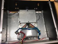
Nice Chokes!
Love the chokes.
Rush
Some chassis work done today.
Still waiting for cinemags
Love the chokes.
Rush
We have MUSIC!
I made a number of foolish errors along the way.
1) Wrong wiring for one SIT. Should have looked for pics of both sides and/or run the traces on the board.
2) Measured across wrong resistor - RB instead of R8. DOH! I need to use the magnifier, good light, and big-old-man glasses
3) Some (maybe) sloppy soldering. P6 was one of the pots that needed to have the legs bent. As I was troubleshooting, I noticed that as I pressed on the pot, the value would change. I reflowed it just in case, and reset it across P4. Also, one of the ground wires had one strand that was not inserted in the through-hole and was wandering across the top. There's no way to know, but it could have easily been touching another component and causing some goofy values. I should have properly tinned all the through-hole wiring first. Sloppy and lazy. Those were the things I found that concerned me when I took the board off and did a thorough inspection.
4) After I FINALLY got both channels to set up properly independently, I spent too much time trying to troubleshoot a short. When I hooked up both channels without the dim bulb tester, I would periodically blow a fuse on power-up. I think I just need the next size up for a fuse. I'll get some 3.0A fuses to replace the 2.5A.
I'm still a little gun-shy to put it in the main system for now. I'll let it cook for a lot longer and re-check before putting it in the system. It seems to take quite some time (several hours) for the Iq to stabilize. It creeps up.
A few questions.
1) Do I need to remove the jumpers to measure and/or adjust the offset or the Iq? I assume, no for both.
2) Do I need to remove the jumpers to measure and/or adjust the buffer values (P6 and P7 adjustments)? I assume, yes for both.
After a good cook, I'll measure, tweak, and seal.
Thank you to Nelson Pass for making these projects possible. It brings me great joy building and listening to these phenomenal amplifiers. I've learned a lot.
Thank you to ZM for making this all possible and all the endless support!
And... a huge thanks to the community, Cal3713 in particular, for the support and help troubleshooting.
Time for more listening on the test rig 😀
Well, never thought I'd be this bad at amp building. One channel had a runaway IQ, started at 200mv and kept climbing until I killed it. Second channel had a short, thankfully I dim bulbed it. Already measured every resistor on one board and double checked a visual match on the other yesterday. Time to give up until some day in the future. Maybe I'll just solder my second set of boards next week and see how they turn out.
Cheer up. Take a break from it and come back again. I am sure the boards are still good.Well, never thought I'd be this bad at amp building. One channel had a runaway IQ, started at 200mv and kept climbing until I killed it. Second channel had a short, thankfully I dim bulbed it. Already measured every resistor on one board and double checked a visual match on the other yesterday. Time to give up until some day in the future. Maybe I'll just solder my second set of boards next week and see how they turn out.
In more positive news, during this process, I installed Zen's recommended motor bypass caps in the amp power supplies of my F4 monos (sharing the case with the sissysit) and quit running them paralleled. They sound great. Better than ever.
Dual mono with an unshared power supplies and film bypass caps (in separate cases) sounds much better than any other combination I've tried (stereo, vertical biamp, and paralleled inputs/outputs).
Dual mono with an unshared power supplies and film bypass caps (in separate cases) sounds much better than any other combination I've tried (stereo, vertical biamp, and paralleled inputs/outputs).
Too bad you've got to pop the top and fiddle around to move between the f4 and sissysit (eventually)... would be fun to just flip a switch and change external cables to go back and forth. Don't want to impact sound quality though.
@Cal3713. You'll get it. There were a number of times I thought about starting over. I only put down the short list of my antics, frustrations, and goofs.
I'd love it if we could just flip some switches between amp boards 😀. I have tried to make things as "modular" as I can. All my connections to the chassis and PSU are either quick connect or through Euroblocks with the exception of my inputs. If all goes well, I can swap out a set of boards in under an hour.
I am considering the motor caps. If I get vertical mounts for the toroids, I may have room. I'll need to do a bit more reading to understand what they do and how to install them. I'm still not quite sure.
Good luck with your troubleshooting!
Well, never thought I'd be this bad at amp building. One channel had a runaway IQ, started at 200mv and kept climbing until I killed it. Second channel had a short, thankfully I dim bulbed it. Already measured every resistor on one board and double checked a visual match on the other yesterday. Time to give up until some day in the future. Maybe I'll just solder my second set of boards next week and see how they turn out.
Cheer up and take a breath for a while 🙂 I had lot's of troubles also, and almost gave up. With Mighty ZM helping me we got everything solved.
I had same feelings as you, I don't know when it became so hard to build an amp. Some of the info is a little scattered around, just read topics through and open new tabs when you find something useful that isn't in the first post.
....... I noticed that as I pressed on the pot, the value would change. ........
that's the case with any trimpot in this world - do not press it , except on setting point
......
1) Do I need to remove the jumpers to measure and/or adjust the offset or the Iq? I assume, no for both.
2) Do I need to remove the jumpers to measure and/or adjust the buffer values (P6 and P7 adjustments)? I assume, yes for both.
.....
1) if you're speaking of setting DC offset and Iq of output stage , you're right - no need to remove jumper at input xformer - there is capacitor in between xformer and OS , anyway
2) as written in post #1 - it is absolutely essential to have jumper removed , until buffer's DC Offset is set
I've reread the thread yet again to see if anyone else has a common question or experience.
I have a nagging feeling that with my lack of true electronics knowledge, but only grade school basics, I may have made another error.
I followed the process for using the CRC in my PSU for setting the output Iq. However ZM shows in the process to use a 0R1 resistor if the power supply is not used.
I have 0R47 resistors in my PSU. If the goal is 0.18A, Should I be setting the voltage across that resistor to ~0.085V instead of the 0.18V?
Edited to add - corrected ZMs recommended resistance notation from 1R to 0R1 for clarity.
Last edited:
- Home
- Amplifiers
- Pass Labs
- Babelfish M25, SissySIT - general building tips and tricks