I had a great chat with my electrical engineer brother-in-law yesterday, and I think I am going to go ahead and try two smps on an amp with the 1000uf cap, I'm still not that great at ordering parts. Does anyone know where to find the power input jack like the one on the back of the ACA, and I'll need a dual pole switch, but I'm guessing there isn't anything like that that will fit on the front? so I may mount it on the back. I'm thinking of wiring it for parallel mono only, so I could clear some space.
Also, we did some listening to the amps in balances mono compared to parallel mono, pretty big difference. Before the mods, balanced was clearly better, balanced does give you more extension up high and a crazy amount of detail. I think I now prefer parallel as the quality of the bass is amazing, and the whole presentation is slight more relaxed with a huge soundstage and sense of space, still with a nice liquid high end.
Also, we did some listening to the amps in balances mono compared to parallel mono, pretty big difference. Before the mods, balanced was clearly better, balanced does give you more extension up high and a crazy amount of detail. I think I now prefer parallel as the quality of the bass is amazing, and the whole presentation is slight more relaxed with a huge soundstage and sense of space, still with a nice liquid high end.
I bought the Meanwell supply from a local supplier and got this type connector, KPPX-4P-SR7DI.
I can see in the diyaudio store that it is an ordinary 2 pol DC jack, 2.1 or 2.5 millimeters on the central stem. Anyone else know?
Search on Mouser for DC power connector panel mount.
As for a two pole DC switch, I don't know what connector to trust with reliable switching DC. I would use a very simple one pole connector that switches a two pole 24V relay. I can be mounted on a very simple board.
Strongbow60: Congrats on a fine build and your refinement in removing startup and ending noise is worthwhile.

Have been able to get all of the upgrade components, most from Mouser, and have 2 questions: is a 1200uf cap, Nichicon AOP 16v OK for the specified 1000uf value? Could only get the 1200uf.
This type of cap is normally in the +- 20% tolerance range, so 1200 is absolutely ok.
Second, the FQH44N10 mosfet is listed as obsolete by Mouser and they offer a FQH44N10-f133. Assume this is an equivalent, but is this right?
It is the FQH44N10-f133 I have as well.
Think this will do for the extra 2-pole case plug -- and give you some extras:
https://www.amazon.com/dp/B08SJM2G5...&pd_rd_r=7f6efe81-e645-41a6-bf0e-e7613d1404a1
Have ordered another Meanwell SMPS; it is GST120A24-P1M; Both DIYAudio and Mouser have them available. Too bad that 1000uf C2 from the original parts is only 16v -- otherwise it could be repurposed as it has been replaced by TungstenAudio's Nichicon RNL upgrade.
The power switch is more of a challenge as the original front switch has a force-fit diameter about 20mm. Wonder if there is a way to use this switch and sent it to a 2-pole converter? Suggestions are always appreciated.
Use a 24V relay instead of a two pole switch. You can solder the leads directly to the pins of a relay if you don't want to use a circuit board.
I will use a relay for my ACA because I could not find a switch that looks resonable, fit in the original switch place, and and still able to handle 3-4 amps of DC.
I will use a relay for my ACA because I could not find a switch that looks resonable, fit in the original switch place, and and still able to handle 3-4 amps of DC.
Thanks again, strongbow60. Will this one do the job?
https://www.amazon.com/Electromagne...9Y2xpY2tSZWRpcmVjdCZkb05vdExvZ0NsaWNrPXRydWU=
Have not done this before so am benefiting greatly from your expertise.
https://www.amazon.com/Electromagne...9Y2xpY2tSZWRpcmVjdCZkb05vdExvZ0NsaWNrPXRydWU=
Have not done this before so am benefiting greatly from your expertise.
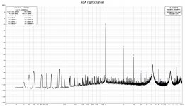
I measured the distortion for my ACA using REW, and I had my suspicion confirmed. Sound is for the most part terrific but there has been some lingering suspicion that there is something not optimal. And today I proved myself right.
For the measurement, output from the ACA was 2.81 V into a 8 ohm resistor. Distortion levels for left and right channel is the same within .1% and the general profile is the same to a fault. I also disconnected the fan's and their power supply, but no change at all.
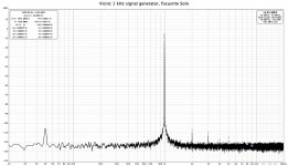
As a reference I attach the output from the signal source, a 1 kHz generator from DIYAudio user Vicnic, in to the ACA and measuring via a Focusrite Solo.
Does anyone has any sort of clue for a mitigation for this high distortion level?
For the measurement, output from the ACA was 2.81 V into a 8 ohm resistor. Distortion levels for left and right channel is the same within .1% and the general profile is the same to a fault. I also disconnected the fan's and their power supply, but no change at all.
As a reference I attach the output from the signal source, a 1 kHz generator from DIYAudio user Vicnic, in to the ACA and measuring via a Focusrite Solo.
Does anyone has any sort of clue for a mitigation for this high distortion level?
Attachments
Last edited:
strongbow60: Cannot help with the potential improvements but can report that this review seconds your data closely:
Archimago's Musings: MEASUREMENTS: Pass Amp Camp Amp (ACA) 1.1. The crossroads between objectivism and subjectivism, and reconsidering von Recklinghausen.
Use REW almost every day with tape recording calibration and such and it is a fine tool. Will be reporting later this week on the multi-smps build and the boards are ready for install.
Which PSU did you end up buying? The lower frequency noise is uncharacteristic of a properly operating SMPS. It also indicates that the filters are not effective. Something isn’t right. The large and broader band high frequency noise spikes are also uncharacteristic of a properly operating ACA.
The ACA works quite well with the 24V kit SMPS. Measurements made with an HP distortion analyzer show an unremarkable residual signal that is dominant with 2nd harmonic and some 3rd harmonic content.
It would be inaccurate to suggest a correlation between these measurements and those of Archimago.
The ACA works quite well with the 24V kit SMPS. Measurements made with an HP distortion analyzer show an unremarkable residual signal that is dominant with 2nd harmonic and some 3rd harmonic content.
It would be inaccurate to suggest a correlation between these measurements and those of Archimago.
Tungstenaudio: Yes, you are correct. Was just looking at the 2nd, third, and continuing harmonic multiple "overshoots" and they are similar to Archimago's graphs. What is different is the level of noise and there strongbow60s graphs are much superior.
Since I listen daily to a 300B SET amp, will be interested in how closely the ACA matches the tube sound with a similar 2nd harmonic "ring."
Got another of the Meanwell 24 volt smps because the goal is to match the two channels as closely as possible. They will be setup as much like each other as is possible. Have the PCBs done and your ears should be ringing from all the praise you received during construction.
Which PSU did you end up buying?
I bought the officially sanctioned SMPS GST120A24 but from a local reseller of Meanwell products. It had another type of connector on the secondary side but otherwise the same unit.
It also indicates that the filters are not effective. Something isn’t right. The large and broader band high frequency noise spikes are also uncharacteristic of a properly operating ACA.
Yeah, something is not right. I tried without the filter and extra capacitor. That is, the SMPS directly to the ACA but no big change. A bit more noise below 1 kHz. I have one other test I will try before bed time.
Just got the multi-smps ACA build finished and its all good news!
The project went together easily and helped by the splendid design/quality of the kit. The case, in particular, is very well made and came from Italy in only 4 days. Here are the changes made for this multi-smps approach:
1. Addition of a second 5.5X2.1 DC power female panel mount; a small piece of lucite was cut with holes at the XLR position and a larger hole added in the center for the plug. Ground wire was added to the case (because of the plastic lucite) to keep all of the chassis ground active.
2. The back switch was re-purposed as a power switch for the second Meanwell smps. This switch has 6 amps capacity at 120V and this is enough for the 5 amp maximum Meanwells. You turn on the left channel with the front switch and the right one with the back switch. Easy enough.
3. All of the power wires use twisted pair 22AWG from the kit; no reduction was made for the ground wires. 22AWG has plenty of amp capacity (7 amps per wire) and its max frequency for 100% skin depth is a high 42khz – so no problems with higher resistance at the extreme treble range.
4. As prescribed by TungstenAudio above, a 1000uf, 35V Nichicon cap was added at the V+/Ground section of the board where the in/out power wires attach – there is enough room for both in each of the 2 holes.
5. All of the wiring for the back panel is direct from the PCB and there is no provision (nor desire) for bridging. Did not want this as am interested in the class A purity possible with a single board.
Tried, BTW, a 24V relay and it was more trouble than worth. Both circuit and electromagnetic relay types have different issues and using, instead, two switches (especially when the second is already available on the back panel) is much more secure.
Wanted to add photos, but have not figured out the URL system asked for here works. My case is the black one and there is not much to show other than the above changes.
Following is a second post for the initial listening tests – one big surprise so far.
Turning the multi-smps ACA on was solid – no problems and the thumps on my speakers are minor. Tried first the output to a pair of older Tannoy Reveals (in case...) and they worked fine but were too soft. Then switched over to my main home speakers, Tekton Double Impacts. These are renowned for their high sensitivity -- 98dB at 4 ohms. Volume perked right up.
While the amp is not a powerhouse, the multi-smps approach has sufficient volume for a large room (with a high enough preamp feed).
Balanced the speakers at 12 volts from IC2/ground as described in the guide and their initial position was rather low – about 8.5 volts. Had plenty of upwards range available from the trimpot and a higher voltage could be dialed in – not certain if this would be bad for distortion or not.
From the initial turn-on, my listening response was “pleasant and refined.” This version of the amp is smooth indeed. Dynamic slams are both powerful and effortless – never a hint of clipping or distortion. Voices are very natural and I can hear subtle nuances not evident on my 300B SET amps (that have, of course, many other advantages).
Have only listened for a couple of hours but the biggest surprise so far is the soundstage. Each voice is very well separated – something I often attribute to damping. However this is accomplished on the multi-smps ACA, each sits precisely alone and is spaced 3D in good depth.
Am going to listen a good bit in the next week to the ACA and will be comparing it to my 300B SET amp and a high-power Emotiva XPA, generation 2, that is high-bias class A for the first 60 watts. Will report on the specifics then. Already, can stress that the ACA sounds nothing like the Emotiva. You will not confuse these two sounds.
BUT it is worth pointing out here that the kit is a true value, not too hard for the first-time builder, and is easy to customize and upgrade.
SO....it's a great deal and Papa deserves my accolades and TungstenAudio my thanks for his thoughtful upgrades – all of which were added to the multi-smps build. KUDOS all, people.
Zamjazz27: The little switch has odd connection patterns. Used the lower-right for the DC power in and the mid-right for the power out to the PCB. Then, when the switch is pulled up it turns on. Both switches on the unit are the same pattern - up is on and down is off. That is, btw, one weird switch on the back...
I suggest you wait until the other half of the VFET lottery has completed, just to see whether the N-VFET amp uses a different PSU filter than the first-to-be-released P-VFET amp. If it is different then you'll have to decide whether you want to copy the P-VFET-PSU-filter, or copy the N-VFET-PSU-filter.
And perhaps it might be possible for you to lay out a super-duper-universal-VFET-filter PCB, which includes both designs. Perhaps as PCB options with wire jumpers or something.
VFET round 2 (N Channel VFET) design is out, and I'm revisiting the suggestion from Mark Johnson that suggested waiting for the N Channel VFET before making the P Channel VFET style filter PCB for the ACA.
VFET P-Channel filter is a single CLC.
VFET N-Channel is Dual RC, one filter for each amp PCB plus a relay to prevent speaker thump. The relay has a little RC delay circuit.
The RC filters use 3x5W 3R3 resistors per channel & 3x1,000uF caps per channel. The 5W resistors seem pretty hefty, but 3R3 should see more voltage drop / power dissipation than 0R47's in parallel, for example.
It looks like speaker output wiring is a fundamental difference between ACA and N Channel VFET amps with respect to this board.
N Channel VFET: Output + is coming off of C1, Output - is GROUND.
ACA: Output + is GROUND, Output - is coming off of C1.
So, for ACA it looks like we will need to connect Speaker Output - to the filter PCB.
I need to pick a relay part number (24V coil, double form C, etc.) and lay out the board. I think I'll go for space for 3x 3W R's per side, and 3x 12.5mm / 5mm pitch caps per side. I'll probably use 0R33 or 0R47's, whichever I have a big stash of. I'll thinking of using the Kemet 1000uF ESK series caps. The 470uF in this series is used in the P089ZB SMPS DC Filter Kit. I understand that series has low ESR and tested quite well. So if it's good enough for that design, let's try it here. And the price is right...
I found a part for a DPST switch that should fit the ACA front plate - Digikey EG5661-ND
So the question is... Single CLC or Dual RC with Relay?
I have a BOM and a PCB laid out for CLC.
I'm going to lay out a PCB for dual RC + Relay.
I haven't thought through "a super-duper-universal-VFET-filter PCB, which includes both designs".
Or perhaps a hybrid approach of dual CLC with Relay?
Thoughts / input?
I'm planning to put the Dual RC + Relay version into KiCAD tomorrow
I'm placing a PCB order in the coming days for several different things, and I want to add the ACA filter boards into that order.
PM me if you'd like to beta test the CLC or Dual RC + Relay PCB in your ACA's. I can also kit up parts and add them to a digikey order I'm making. I'll be ordering those parts early next week.
I'll ask for cost of PCB/parts + shipping/paypal fees for beta testers.
The ACA resembles the first P-type VFET amp in that the active signal transistor Q1 is isolated from the power rail by the current source. It has much less of an issue with turn-off thump. The main part of the new VFET filter board that will be beneficial for the ACA is the separate RC network for each channel. Adding extra capacitance to the power rails of the first FET amp reduced the turn-off thump to near zero. So the inductor may not be necessary, but it’s certainly up to you if you want to keep it.
- Home
- Amplifiers
- Pass Labs
- ACA amp with premium parts