Hi, why the 33µF coupling cap? you can use one of fraction of this value without low pass effect 1µF is fine or 0.5µF. And this could be non polarized.
Also you can avoid the use of the first buffer. The amplification amount is <1, it has input high impedance, near the same of the valve.
Try to use a cascade buffer without cap between the stages.
Best Regards
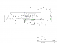
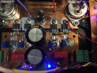
Your comments pushed me to modify the $8AUD EBay preamp, only one coupling capacitor.
2mA CCS for the 6J1 with 58V plate voltage.
Cheers
.
Attachments
Excellent Nuvistor preamplifier thanks Pascal for video show.
Salutations 😀
Coucou, must I say kikoo?
Having lot of fun and low cost to approach “Mr Pass intellectual properties”.
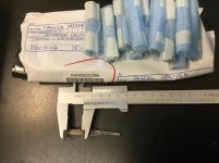
Just receive a dozen of miniature VFD, a kind of American Nixie tube from Russia.
The heater direct cathode is merely 17mm, hope that it will raise the resonance frequency above 5kHz to match with the Korg 6P1.
My nuvistor resonance is about 8.5 kHz.
Cheers
.
Attachments
…
Did you buy a Soviet caliper as well?
Vodka too!!!
Here is my completion of a $1.41AUD VFD
Cheers
Attachments
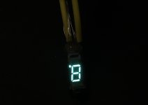
The Spectacular BF B1 with 8.8. VFD triode harmony. Far Easterns consider 88 to be auspicious, brings lots of good luck. Perhaps there is a nice way for the 88 to somehow be visible through a window opening or something. Could find a huge market in the Far East. Way better than a couple of small faint rectangles. 🙂
Commonwealth inhabitants, living at islands, strictly in accordance to statistics, outdrink russkies at any given moment. They just have to buy vodka, as auxiliary to a caliper or just an opposite. Who knows. You did it so you know better.
Cheers
Cheers
IV-8 VFD as triode
My IV-8 driver has a funny character, the gain is only 6dB.
Hi,
I believe you have more luck than you can chew, due to the tube name is IV-8.
Well, hurry up, the lunar new year is just only a stone throw away.
One can use the IV-8 as a dummy fluorescent or dynamic one with log amp driver as “lucky Vu meters”.
Cheers
I cannot recall if the caliper came first or the vodka, for sure I won’t buy them again, due to caliper quality, it last forever.
The vodka, only a bottle, then I drop back to my favorite Grey Goose’s.
Cheers
YouTube
.
My IV-8 driver has a funny character, the gain is only 6dB.
The Spectacular BF B1 with 8.8. VFD triode harmony. Far Easterns consider 88 to be auspicious, brings lots of good luck. Perhaps there is a nice way for the 88 to somehow be visible through a window opening or something. Could find a huge market in the Far East. Way better than a couple of small faint rectangles. 🙂
Hi,
I believe you have more luck than you can chew, due to the tube name is IV-8.
Well, hurry up, the lunar new year is just only a stone throw away.
One can use the IV-8 as a dummy fluorescent or dynamic one with log amp driver as “lucky Vu meters”.
Cheers
Commonwealth inhabitants, living at islands, strictly in accordance to statistics, outdrink russkies at any given moment. They just have to buy vodka, as auxiliary to a caliper or just an opposite. Who knows. You did it so you know better.
Cheers
I cannot recall if the caliper came first or the vodka, for sure I won’t buy them again, due to caliper quality, it last forever.
The vodka, only a bottle, then I drop back to my favorite Grey Goose’s.
Cheers
YouTube
.
Attachments
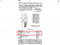
Well it spells like Indicator Vacuum #8. ИВ-8 in Russian.
Does it resonate or it does not?
You have plate loaded by 330k, however plate current specified should be around 1.5mA @ 20VDC. I think because grid surface area is comparable to the plates' one a lot of electrons are intercepted before reaching the anode. Thus small gain. My coarse on gas discharge and thermionic devices was about 40 years ago - I can't advise you on that.
At the datasheet grid current is on par with the plate one.
Heater voltage should be 0.85 which is quite higher than you put at the schematics of yours
Last edited:
Well it spells like Indicator Vacuum #8. ИВ-8 in Russian.
Does it resonate or it does not?
...
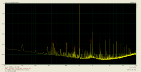
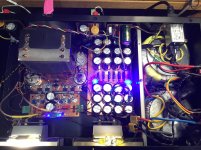
Of course, it does, but tolerable due to resonance frequencies (255Hz, 510Hz and 765Hz) are below -80dB, the IV-8 has a rigid mounting and is submitted to transformer and speaker vibration.
Will built a micro vibration isolator as a mounting bed for those tubes.
Here is “The Sound of Sovietic Indicator Vacuum #8” in a rigid bed.
YouTube
.
Attachments
Did you fixed heater voltage? Rigid mount on heavy copper/iron plate will ease microphonics for sure.
...
You have plate loaded by 330k, however plate current specified should be around 1.5mA @ 20VDC. I think because grid surface area is comparable to the plates' one a lot of electrons are intercepted before reaching the anode. Thus small gain. My coarse on gas discharge and thermionic devices was about 40 years ago - I can't advise you on that.
At the datasheet grid current is on par with the plate one.
Heater voltage should be 0.85 which is quite higher than you put at the schematics of yours
Hi alexberg
Based on IV-8 spec, my heater at 0.75v is within limit, quite on the margin.
I am lucky enough to have an 7809 and a pair of 180 Ohm resistors at hand to drop the voltage down to 0.75V. (Now I start to believe number 8 will bring luck, hihi)
In my circuit the IV-8 is not acting as an indicator, so plate And grid voltage have to be selected for minimum distortion where a cancellation of H2 and H3 occurred, then a shifting up or down would do to the coloration of personal musical taste, where I learn from Mr Pass.
Did you fixed heater voltage? Rigid mount on heavy copper/iron plate will ease microphonics for sure.
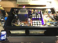
I thought in an opposite way, rigidity will convey vibration from main transformer (and CPU fan), plus amplifier’s case will acting as elephant ears to speakers surrounding.
Isolation from those vibrations is a solution to my believe.
Cheers
Attachments
Sound very nice 🙂 Congratulations !
Thanks mate,
Sound nice like a remix, due to all ambient noises are within the amplifier circuit.
Will try to use very flexible wire ( earplug wire) to do the connection for the tubes, hope more natural sound will be produced.
Plate has to be decoupled from the chassis like low noise fans i.e. using silicone rubber "suspenders".
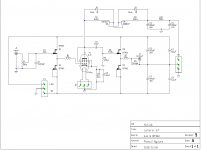
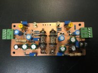
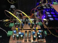
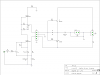
Final Release DN2540 Direct Coupling
My final version has only 4 transistors, 4 capacitors, 9 resistors and 2 trim pots.
Direct coupling from driver stage also provides the necessary bias voltage for the THF-51S and BUZ905D.
Thank you:
Mr Pass for all valuable lessons that helped.
Mr Haïk Kokorian, DN2540 with floating power supplies.
Mr Dady, THF-51S introduction to Pass Labs’ forum.
Mr Alexberg, fun with VFD.
I will disappear for a while, best wishes to all.
.
Attachments
-
 B2720BF8-9BA9-414E-85EB-093258380A02.png51.7 KB · Views: 587
 -
 D3B8D235-0FCE-4195-B487-2DA241C65DEF.jpg886.2 KB · Views: 555
 -
 D50D4BCE-449A-42F3-9D10-5BFC04BC7931.jpg944.2 KB · Views: 533
 -
 E47FFD61-C744-4E33-9DE4-61A896E5A4B7.jpg867.6 KB · Views: 521
 -
 9A7CA5EE-EF89-4C1E-8904-F9D2AA202752.jpg717.5 KB · Views: 305


Dear Pascal, What you think in try to see a floating PS for the final stage? In this form you avoid the use of the output cap.
XSIT, a SIT-3 cloning
@SoundHappy
@ZenMod
Thanks for your comments, the Shunt Regulated Push Pull driver stage has a problem, I put it together in a hurry just a few hours before my holiday.
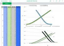
Good to be back, just have a listen in comparison with my SIT-3 clone (LateSit), thé sound is inferior, loss of high frequency, no match with my “SIT-3”.
I track the bandwidth, above 10kHz, it is devastated, like I have a built in low pass filter. Some sort of Miller effect in which the Cgd is multiplied, I supposed.
Hi dady, hope you have had a wonderful moment with Christmas and New Year celebrations.
My next project is a SIT-3 clone with floating PS, that help me to have a direct coupling from the input jack to speaker terminals.
The project will be named as XSIT, you will know why, by looking at the illustration attached.
Wonder why nobody asked me how do I match the output transistors?
.
@SoundHappy
@ZenMod
Thanks for your comments, the Shunt Regulated Push Pull driver stage has a problem, I put it together in a hurry just a few hours before my holiday.
Good to be back, just have a listen in comparison with my SIT-3 clone (LateSit), thé sound is inferior, loss of high frequency, no match with my “SIT-3”.
I track the bandwidth, above 10kHz, it is devastated, like I have a built in low pass filter. Some sort of Miller effect in which the Cgd is multiplied, I supposed.
Dear Pascal, What you think in try to see a floating PS for the final stage? In this form you avoid the use of the output cap.
Hi dady, hope you have had a wonderful moment with Christmas and New Year celebrations.
My next project is a SIT-3 clone with floating PS, that help me to have a direct coupling from the input jack to speaker terminals.
The project will be named as XSIT, you will know why, by looking at the illustration attached.
Wonder why nobody asked me how do I match the output transistors?
.
Attachments
- Home
- Amplifiers
- Pass Labs
- LateSit